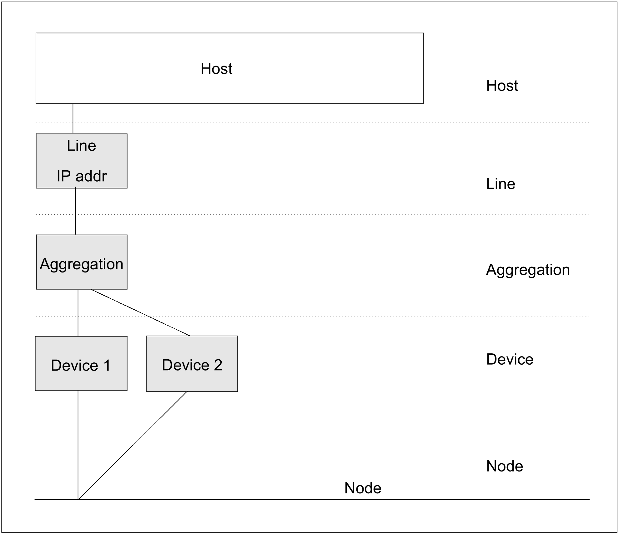
The example shows how two devices (VLAN devices) are aggregated. Only one IP address and one MAC address which are assigned to the link aggregation are visible to the outside. You enter the IP address when defining the line. BCAM and the device connections interwork to distribute the load over the individual devices.
Definition of the link aggregation
/CREATE-LINK-AGGREGATION AGGREGATION-NAME=AGGRE#01
/CREATE-VLAN-DEVICE DEVICE-NAME=D#AGG#A1, -
/WRITE-DEVICE=AA01,READ-DEVICE=AA02,AGGREGATION-NAME=AGGRE#01
/CREATE-VLAN-DEVICE DEVICE-NAME=D#AGG#A2, -
/WRITE-DEVICE=AA03,READ-DEVICE=AA04,AGGREGATION-NAME=AGGRE#01
/CREATE-NODE NODE-NAME=NODE#VA1,LAN-TYPE=*VIRTUAL(VLAN-ID=*UNTAGGED)
/CREATE-VLAN-LINE LINE-NAME=L#VLAN#1,NODE-NAME=NODE#VA1, -
/IP-ADDRESS=172.25.92.77,AGGREGATION-NAME=AGGRE#01, -
/ MAX-LPDU-SIZE=*BY-DEVICE
Activating the link aggregation
/ACTIVATE-LINK-AGGREGATION AGGREGATION-NAME=AGGRE#01
/ACTIVATE-VLAN-DEVICE DEVICE-NAME=D#AGG#A1
/ACTIVATE-VLAN-DEVICE DEVICE-NAME=D#AGG#A2
/ACTIVATE-VLAN-LINE LINE-NAME=L#VLAN#1
/BCACT NODE=NODE#VA1
Note
Instead of the *UNTAGGED specification for a VLAN ID in the CREATE-NODE command, you can also assign a VLAN ID. The specification *UNTAGGED corresponds to a normal line. Assigning a VLAN ID leads directly to a VLAN configuration.