In the following a redundant VLAN configuration is presented using only BCAM commands. For definition purposes VLAN-capable devices are used which can be defined as tagged or untagged.
Dynamic generation
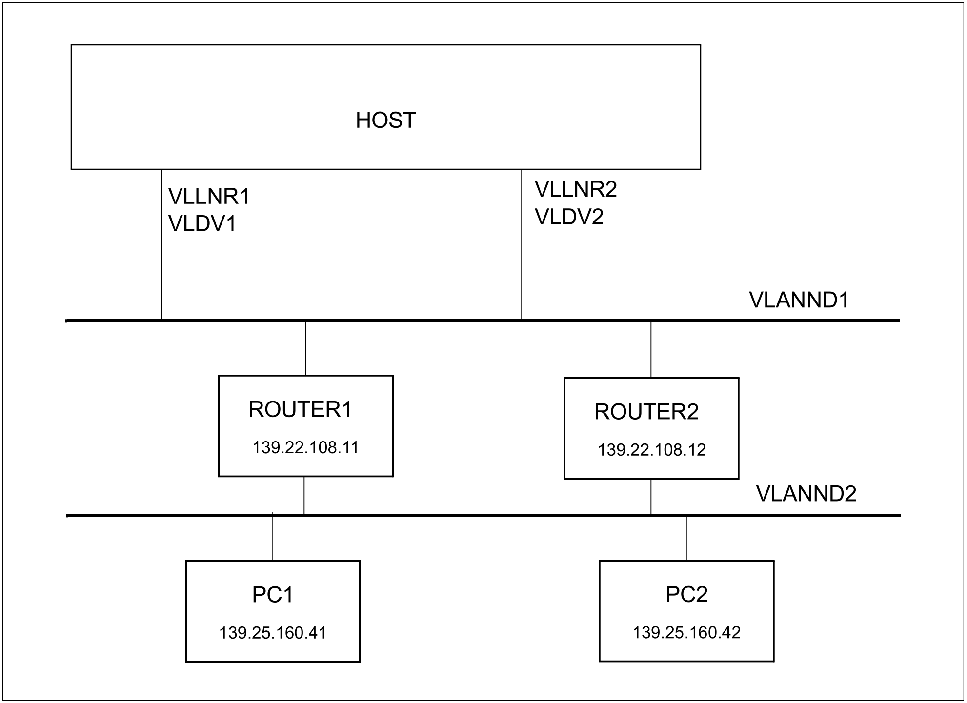
/REMARK Definition of the VLAN devices VLDV1 and VLDV2
/REMARK Definition of the VLAN node VLANND1
/REMARK Definition of the VLAN lines VLLNR1, VLLNR2
/REMARK Definition of the router and remote processor
/CREATE-PROCESSOR PROCESSOR-NAME=ROUTER1
/CREATE-ROUTE ROUTE-NAME=ROUTER1,-

/            PATH=*NODE(NODE-NAME=VLANND1,-

/            L3-PROTOCOL=*IP(IP-ADDRESS=139.22.108.11))
/CREATE-PROCESSOR PROCESSOR-NAME=PC1
/CREATE-ROUTE ROUTE-NAME=PC1,-

/            PATH=*VIA-ROUTER(ROUTER-ROUTE-NAME=ROUTER1,-

/            L3-PROTOCOL=*IP(IP-ADDRESS=139.25.160.41))
/CREATE-PROCESSOR PROCESSOR-NAME=ROUTER2
/CREATE-ROUTE ROUTE-NAME=ROUTER2,-

/            PATH=*NODE(NODE-NAME=VLANND1,-

/            L3-PROTOCOL=*IP(IP-ADDRESS=139.22.108.12))
/CREATE-PROCESSOR PROCESSOR-NAME=PC2
/CREATE-ROUTE ROUTE-NAME=PC2,-

/            PATH=*VIA-ROUTER(ROUTER-ROUTE-NAME=ROUTER2,-

/            L3-PROTOCOL=*IP(IP-ADDRESS=139.25.160.42))