The following terms have been used frequently in this manual. They are explained below:
activation
Whenever a task issues a request to the system after a period of inactivity (e.g. think time at a terminal), the system must take two decisions before processing can be continued:
1. The activation decision
2. The initiation decision
activation decision
This decision gives the task the right to use the CPU and to perform I/O operations.At activation time, the task is allocated as many main memory pages as it is likely to need.
Activation delays are possible in cases of resources overloading.
assignment of paging activities to the initiating task
The system initiates all paging I/O operations directly in the SIH state. However, SM2 does not assign all paging I/O operations to the SYSTEM category, but sometimes to the initiating task.
For SM2, the initiating task is that task which caused a page fault during page access.Two chains have to be distinguished:
Only one page is read.
The full firmware duration of the output operation is assigned to the initiating task and its category. The full software duration of the input operation is assigned to the category of the initiating task.
The task and category counters for the number of paging operations are incremented by 1.Only page output occurs.
The full firmware duration of the output operation is assigned to the PGE task, but not to the SYSTEM category (although it is registered system-globally for SUM). The PGE task counter for the number of paging operations is incremented by 1.
background storage
Storage area on peripheral devices which can be accessed by means of virtual addressing. Programs and data are transferred in pages from background storage to main memory before processing and returned (if required) to background storage after processing.
Big Pages
Big Pages (4 MB) are used for JIT compilations for a better performance on x86 servers.
caching
Caching is understood to be the process of buffering data in a fast data medium (the cache) in an attempt to accelerate subsequent inputs and outputs to the same data areas.
Data to be written to or read from disk is buffered in the cache to avoid the longer input/output times involved in accessing the disk.
If the data to be accessed is in the cache at the time of access, this is referred to as a cache hit, otherwise as a cache miss.
The proportion of hits in the total number of accesses is known as the cache hit rate. The higher the hit rate, the greater the advantage of using the cache. The hit rate which can be achieved depends on a range of factors, such as the locality of the accesses, the size of the cache, the caching method selected (read cache, write cache, read/write cache) and the appropriate selection of files. Monitoring systems such as SM2 can be used to identify files and disks suitable for caching.
counting of I/O operations and their duration
For SM2, an I/O operation is
- any version of EXCP (EXCP, EXCPW, $EXCP, $EXCPW) or
- an I/O request from the memory management system for paging (no SVC call) addressed to the I/O control module. The I/O control module is the central system component for handling physical I/O operations.
The I/O control module normally processes the I/O request with one privileged instruction (Start Device or Start Subchannel). For each instruction a termination message is issued, upon which the I/O operation is counted.
In rare cases (e.g. disk connected to a channel operated in selector mode), two SDV instructions are issued. This is called “offline seek”. The first SDV prepares the I/O device and the second initiates the I/O operation proper. Only one I/O operation is counted in this case too.
The following particularities should be noted:
I/O requests which could not be started properly (SDV with condition code differing from 0) are ignored.
So-called SENSE SDVs, which are generally issued after an I/O request that resulted in an error and serve to fetch additional diagnostic information, are only included in report 100.
In SDV fast release mode supported in some servers, a properly initiated I/O operation can be rejected at a later time by a channel. The rejected SDVs are not counted.
In determining the duration of the I/O operation, the time between the SDV and the termination message is always counted. An SDV rejected because of an error is ignored; this results in an increase in waiting time for the device. An SDV rejected in SDV fast release mode is ignored; this also results in an increase in waiting time for the device.
In “offline seek” mode, the time between the first SDV and the termination message for the second SDV is counted.
CPU states
Program interrupts are caused by
input/output requests
calls to the Control System
timers
errors
paging requests
The system distinguishes between the following CPU states when handling programs and interrupts: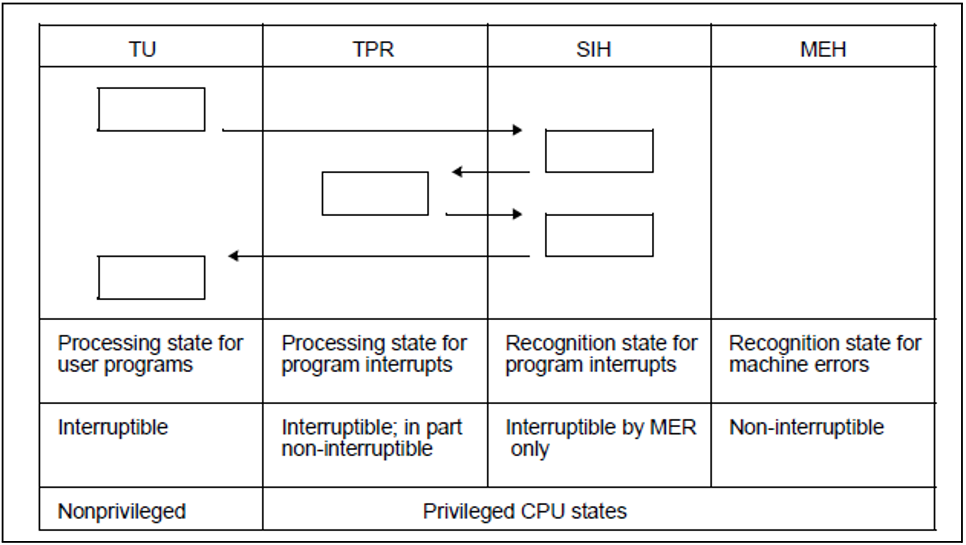
CPU states
If the CPU is in none of the above states, it is in the IDLE state.
deactivation, forced deactivation
When a task is deactivated, it is no longer authorized to use the CPU. In the case of forced deactivation, the system withdraws the task’s right to use the CPU.
Forced deactivation can occur when resources are extremely overloaded.
dilation factor
Dilation factors can be determined for individual tasks, for specific task classes and on a system-global basis.
Dilation factor = Dwell time / Productive RST
Productive RST = productive CPU RST + productive I/O RST
For further information on productive RST, see “time equivalent for the productive performance” on page 633.
A dilation factor smaller than 1 can occur when a task uses asynchronous I/O. In this case, the task uses 2 or more resources simultaneously.
The dilation factor output in SM2R1 report 57 is not comparable with the value “REQUEST DELAY” in the SM2 PCS report and in SM2R1 report 74. This quantity is designed for optimum response time control by PCS.
DMS I/O operations
All accesses to peripheral devices not performed for paging.
dwell time
The time spent by a task in the system comprises the service times of the physical resources and all non-voluntary wait times of the task.
It is not always possible to distinguish between voluntary and non-voluntary wait times without unreasonable outlay.
Example
The BS2000 boursing mechanism can be used to determine both the voluntary wait times (e.g. wait for user input) and the non-voluntary wait times (wait for a busy resource).
For simplicity’s sake, SM2 considers all waits times for boursing, for the PASS and VPASS macros, and for responses to a console question (/INFORM-OPERATOR WAIT-RESPONSE=*YES or TYPIO macro with response) as voluntary wait times.
SM2 includes the following times in the dwell time:
Time spent in the queue for the CPU(s).
This includes the CPU RST and the time spent in Q1.Wait for paging page transfer (time spent in Q3).
Wait for execution of DMS I/O operations (time spent in Q4 and Q12 for I/O).
Further time spent in Q4 except for boursing, ITC, PASS/VPASS and waiting for response to console questions.
Wait for activation (time spent in Q5).
Wait for admission (time spent in queue Q6).
Wait in Q7 for hardware error recovery (HERS).
Further time spent in Q12 except for boursing and waiting for response to console message.
Hardware duration of I/O operations for paging page transfers.
EXCP
Macro on the physical I/O level which initiates a channel program (see “counting of I/O operations and their duration” on page 623).
hardware service time
Time for which devices are busy with I/O operations, also called hardware duration. The hardware duration is defined as the time between I/O initiation (start subchannel) and device end (interrupt).
See also “service times definition (DCS, I/O operations)” on page 631.
initiation
After a task has been activated, the system must reach a decision on initiation. When it is initiated, the task can use a CPU, i.e. compute.
input/output, logical level
On the logical level, the user uses macro calls (e.g. GET, PUT) to initiate system functions which control data interchange with the peripheral devices, block and unblock data, and handle any errors that may occur.
interaction
Generic term for wait, response, think, and transaction processes (RESPONSETIME monitoring program).
main memory
Memory area which can be addressed directly by the CPU. The program instructions are read and processed in this area.
overall performance
The productive performance and the dilation, i.e. the relation between the time spent in the system (dwell time) and the time required for providing the productive performance, are important criteria for accessing the suitability of an IT system for a given load.
The following definition is used:
Overall performance = productive performance + housekeeping performance
Productive performance is the load handling capacity.
Housekeeping (or overhead) performance is the performance required for system control by the operating system.
Overall performance is the sum of these two quantities.
The performance is provided by the various IT system components, e.g. the CPU(s) and the peripheral devices.
Performance = work done per unit of time. A precise definition of “work done” is not attempted here. Only the time required for productive or housekeeping performance is considered.
The time equivalent of the productive performance or of the housekeeping performance is the (service) time for which resources are being used for productive work or for housekeeping.
It is also called Resources Service Time (RST).
The dwell time of a task is the sum of the physical resources service times plus all nonvoluntary wait times of the task. The non-voluntary wait time of a task is thus a criteria for task obstruction by other tasks in the system.
page fault
BS2000 is an operating system with virtual addressing, i.e. it supports several address spaces simultaneously. The virtual address spaces and the real main memory are managed in units of 4-Kb pages. (On x86 servers, a part of the main memory is also managed in 4-Kb pages.) The DEMAND PAGING method is used for mapping virtual pages onto real memory page frames:
When an attempt is made to access a page that is not in main memory, the hardware detects this condition and uses a page fault interrupt to notify the operating system. If the addressed page is on disk (paging device), the page is read in (page transfer).
If free page frames are required, the system tries to return modified main memory pages to disk.
SM2 counts the number of paging I/O operations (number of I/O requests to the centralI/O control module of the system, which corresponds to the EXCP calls). This number is supplied in the ACTIVITY report and in SM2R1 reports 3 and 4.
For each I/O request, SM2 increments this number by 1 when
a page is read in or
one or more pages are written (the system tries to group up to 8 pages for one I/O operation).
The number of pages written is also given in the MEMORY report and in report 55, and the number of pages read is given in report 56.
SM2 supplies the following additional data:
Total number of page fault interrupts. “Real” page faults are not included in this number.
Number of page fault interrupts for which the addressed page was still in main memory (PAGE RECLAIMS).
Number of page fault interrupts for which a page transfer is required. This count is also incremented when 2 or more tasks try simultaneously to access the same virtual page and the page is not in main memory.
Number of page fault interrupts for the first access to a new page.
paging in BS2000
Many a time, the number of addressable virtual pages is greater than the number of page frames available in main memory.
For the removal of pages which can no longer be kept in main memory, see “page fault” on page 628.
The main memory management strategies are based on the assumption that the programs (or tasks) will only address a limited set of the total number of virtual pages within a specific period of time, i.e. that the programs are more or less local. This set of pages, whose size varies dynamically, is the called the working set.
The PPC (planned page count) indicates how local a program or task is. This value is provided by the memory management system before task activation and – because it is a measure of the intensity of memory utilization by the task – is used as a task activation criterion.
The PPC value for the next activation phase depends on program behavior during the preceding activation phase.
While the task is active, the PPC value can be modified in accordance with program behavior.
The number of pages used by a task is called UPG (USED PAGE COUNT).
The main memory is managed system-global (real memory management). This means that, when determining the pages which should be removed because of a shortage of free real-memory page frames, all main memory pages are checked.
The LRU principle is used for determining the pages to be removed from main memory:To this end the main memory pages are sorted according to their access times.
The PPC value is supplied as a measure of how local a task is.
The check is made and working set pages are removed only if free page frames are required. This is why UPG may become greater than the working set, especially if the main memory is large.
Free pages or pages not actually assigned to a task are in the FREE POOL (read-only- or read-write-queue) or in the empty queue.
paging I/O operations
All I/O operations performed in response to paging requests.
paging memory
The whole main memory area available to all users for paging.
paging rate
Number of required paging I/O operations per second (calls to the I/O control module).
PAV
Parallel Access Volume
The PAV function allows a number of I/Os to be executed simultaneously to a logical volume. This increases the data rate for volumes with high utilization.
PDT
The PDT (Physical Device Table) is the central device table of the input/output system which contains an entry for each device. In addition to the device name and type, the entries also contain details about device characteristics which must be borne in mind when the devices are operated.
PGE task
System task required for restarting after hardware errors during paging I/O.
response time
Time required by the system for processing a request. For the user, this is the time between an input operation and the corresponding system response
(see section “RESPONSETIME Monitored data on the BCAM pool” on page 59 and section “BCAM-CONNECTION Monitored data on connection sets” on page 48).
RSC IOs
The term RSC IO (I/O request with “Remote System Call” on x86 servers) refers to the execution of an I/O request with a high-performance interface between BS2000 and X2000.
BS2000 defines the I/O request in the “open” format expected by the FC peripherals. This format enables multiple I/Os to be started in parallel with disks.
service times definition (DCS, I/O operations)
Detailed monitoring of service times is possible on XS systems with DCS, the interface between the operating system, the I/O processor and the physical devices.
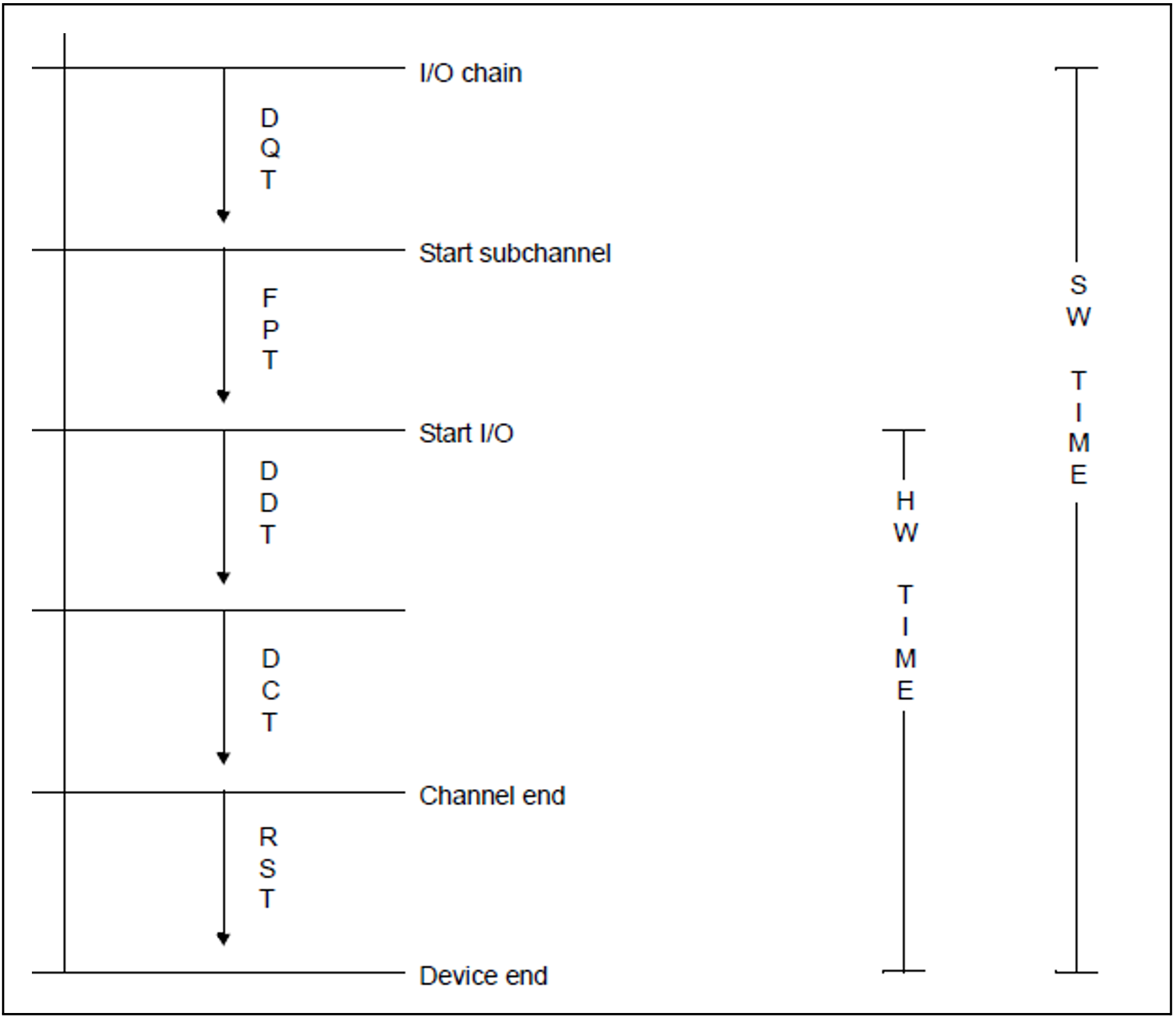
Service times
Service time | System | Definition |
DQT | SM2 | Time from the I/O chain to the subchannel start |
FPT | DCS | Time from the subchannel start to I/O start |
DDT | DCS | Physical positioning time |
DCT | DCS | Data transfer time |
RST | SM2 | Time from channel end to device end |
software service time
The software service time (also called software duration) is obtained by adding the waiting time of an input/output request in the device queue of the system to the hardware duration. See also “service times definition (DCS, I/O operations)” on page 631.
queues
Q0 | A task is in this queue when it is using the CPU. |
Q1 | Tasks in this queue are waiting to use the CPU. |
Q2 | This is the queue for the SM2 write task. |
Q3 | Tasks waiting for end of paging. |
Q4 | Tasks waiting for peripheral I/O termination (disk, tape), for task communication |
Q5 | Ready tasks waiting to become active again. |
Q6 | .Ready tasks waiting to be admitted (PCS). |
The task queues described in the following contain tasks waiting for an event that is very remote in time before they become ready. These tasks are deactivated, i.e. they have lost the right to use main memory.
Q7 | Not used |
Q8 | Not used |
Q9 | Not used |
Q10 | Hold queue for tasks placed in the hold state by the system or the operator in an |
Q11 | System tasks which are not called on a time basis. |
Q12 | Tasks in the WHEN queue or tasks waiting for an event remote in time, e.g. |
Q13 | Tasks waiting for VPASS or PASS end. |
The task queues are implemented by chaining the TCBs (task control blocks). In the system, a separate entry refers to the first TCB of each queue.
Task queues Q0 to Q4 exist once for each central processor. Queues Q5 to Q13 are system-global.
time equivalent for the housekeeping performance
The housekeeping performance of the system is a measure of the operating system overhead caused by the workload to be processed. Its definition encompasses the following factors:
CPU service time (SIH time) for processing paging requests.
Further SIH times for the operating system.
This is for simplification only, because various operations performed in the SIH state constitute productive work. Part of the productive performance for I/O execution occurs in the SIH state. System activities for processing SVC calls (SVC frame processing) are also handled in the SIH state. As far as monitoring is concerned, it would be very complicated to assign the SIH part of the productive performance to the individual tasks.Hardware duration of the I/O operation for paging page transfers.
time equivalent for the productive performance
In determining the RST (resources service time), a distinction is made between the CPU and the peripheral devices as follows:
For the CPU the RST is the time in which instructions are processed in the TU and TPR states. This time is called productive CPU RST (the SIH share of the productive performance is not counted; see above).
For the peripheral equipment, the RST is the firmware service time of the devices for performing an I/O operation.
The firmware duration is defined as the time from I/O initiation (START-DEVICE or START-SUBCHANNEL instruction) to I/O termination (channel interrupt). Only I/O operations initiated by DMS are counted. This share is called productive I/O RST.In practice, this firmware duration depends on multiple factors. For example, access time for disk access highly depends on whether the data is already stored in the disk controller's cache. This is affected by the history and cache strategy for the disk controller. Previous access to the same data or neighboring data can lead to storage in the cache. This firmware duration is also affected by the controller's utilization. This utilization determines how long data remains in the cache.
By adding the waiting time of an I/O request in the device queue of the system to the firmware duration, the software service time (also called software duration) is obtained.
transaction
Total number of system responses to a user request.
(Please refer to the normal usage in the UTM manuals for the meaning of the term “transaction” in the UTM reports).
virtual address space subdivision
The virtual address space is subdivided as follows:
Class 1 memory
Resident memory for system module code.
The size of this memory segment is specified at system generation time and remains constant for the session.Class 2 memory
Paging memory for system module code.
The size of this memory segment depends on generation specifications and remains constant for the session.Class 3 memory
Resident memory requested dynamically for tables, control blocks and overlay modules.
The size of this memory segment varies during the session.Class 4 memory
Paging memory requested dynamically for tables, control blocks and overlay modules (also shared modules).
The size of this memory segment varies during the session.
working set
see “paging in BS2000“