The Brocade ICX 7750-26Q has the following LEDs on the front panel:
Two power supply units (PSU) with bicolor status LEDs (green and amber) labeled PSU1 and PSU2
One DIAG LED with bicolor status (green and amber) provides information about the diagnostic status
One MS LED with bicolor status (green and amber) provides information about master/slave mode
One HA LED with bicolor status (green and amber) provides information about highavailability mode
One RDNT LED with bicolor status (green and amber) provides information about redundant mode
Four bicolor status LEDs (green and amber) for each of the 26 QSFP+ ports that indicate the status of the ports in 40 GbE mode and 4x10 GbE breakout mode.
The figure 13 shows the LEDs on the Brocade ICX 7750-48F front panel.
The up-arrow port status LEDs for the 10 GbE ports correspond to the upper, oddnumbered ports. The down-arrow port status LEDs correspond to the lower, evennumbered ports.
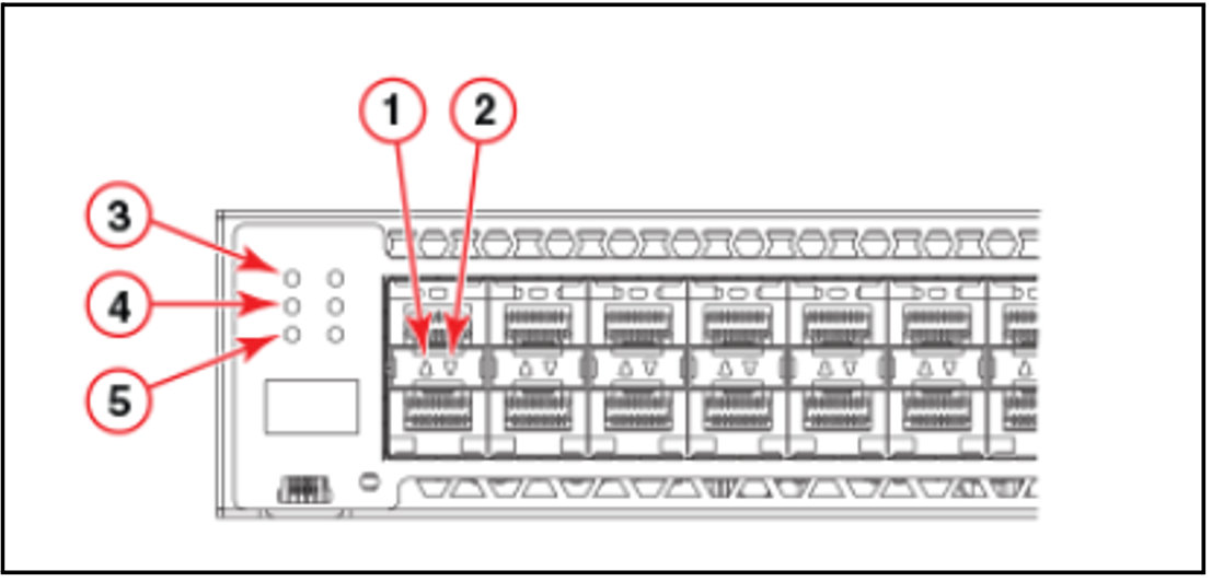
Figure 13: Net Unit (ICX 7750-48F) LEDs (front panel)
Explanation:
1 | Upper 1/10 GbE port LEDs |
2 | Lower 1/10 GbE port LEDs |
3 | PSU1 and PSU2 status LEDs |
4 | MS and DIAG status LEDs |
5 | HA and RDNT status LEDs |