At the front of the basic rack on the SE700 and SE500, a control panel is located on the outside. The control panel is connected to the service processor (SVP) of the SU700 / SU500 of the SE server.
Further information on the SU700 and SU500 is provided in the "Server Unit /390" Operating Manual [2].
The physical layout of the control panel is shown in the figure below:
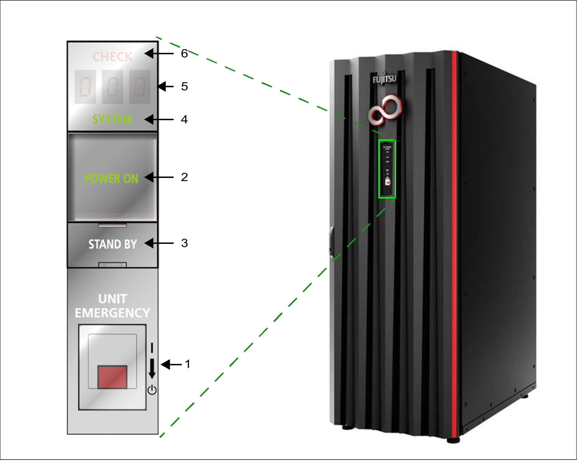
Figure 7: Operating panel on the rack of the SE700 / SE700B and SE500 / SE500B
The control panel contains the following controls and displays (please refer to the numbers in the figure):
UNIT EMERGENCY switch
The UNIT EMERGENCY switch switches the SU /390 off.POWER ON button with lamp
Switches the Server Unit on. When the SU /390 is switched on, POWER ON lights up green.STAND-BY button
Switches the SU /390 off, but not currentless (power supply units in standby mode).SYSTEM lamp
Displays whether the CPUs of the SU /390 are active.CHECK lamp
Shows whether a fault has occurred.STATUS indicator
Supplies detailed information on the hardware status.
The function of the displays and controls in the operating panel is described in the sections below.