Global error indicator and CSS indicator
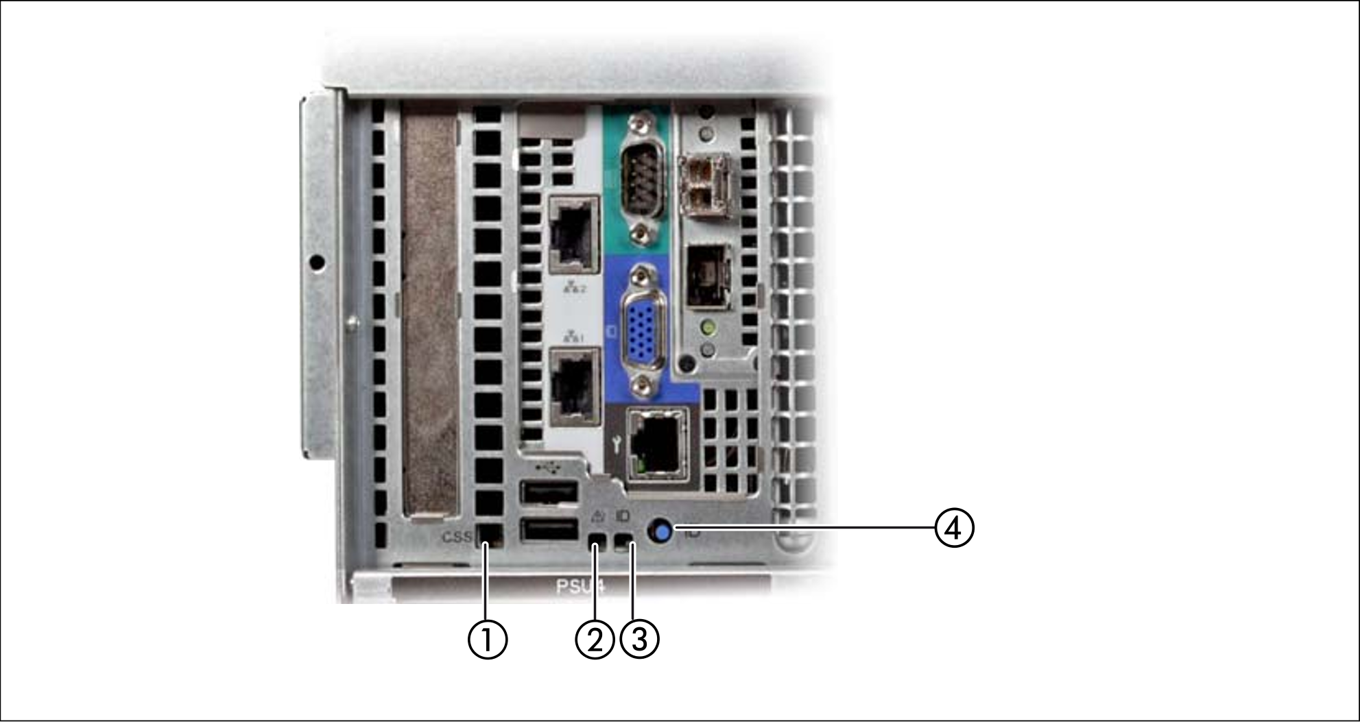
Figure 5: Global error indicator and CSS indicator, ID button and ID indicator
No. | Meaning |
1 | CSS indicator (yellow)
If the event is still acute after the Server Unit has been switched on/off, the indicator is activated after the restart. |
2 | Global error indicator (yellow)
If the event is still acute after a power failure, the indicator is activated after the restart. |
3 | ID indicator (blue)
The ID indicator can also be activated via the ServerView Operations Manager and the iRMC web interface, and the status can be reported to the ServerView Operations Manager and the iRMC. |
4 | ID button |
LAN ports
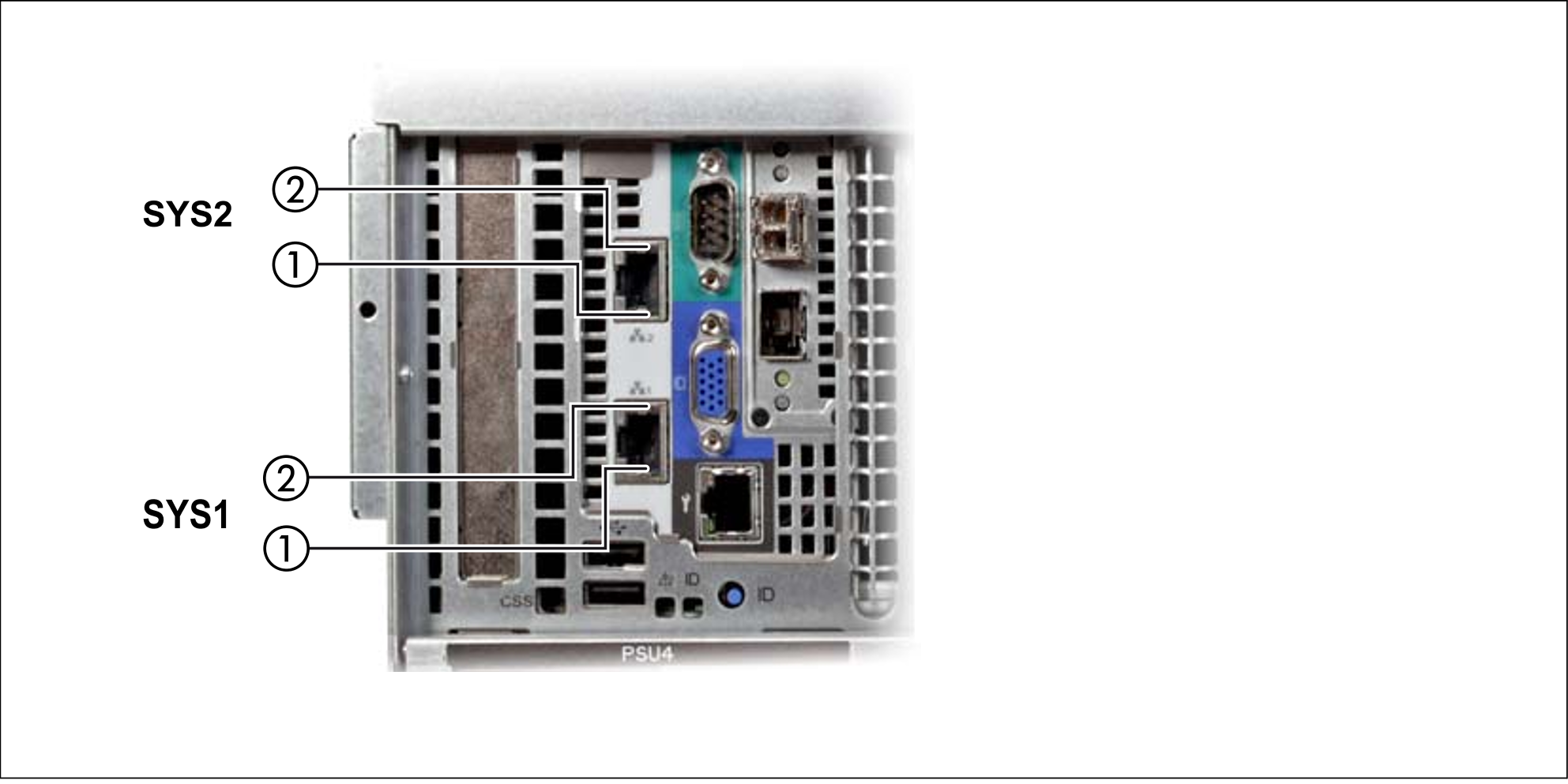
Figure 6: LAN indicators
No. | Meaning |
1 | LAN link/transfer
|
2 | LAN speed
|
The MAC addresses entered on the green ID card refer to LAN #1 (SYS1) and #2 (SYS2).
The MAC addresses of LAN ports #3 (not used) and #4 (not used) are then the next two MAC addresses in ascending order. The green ID card is located on the front of the Application Unit, see item 1 in figure 1.
Indicators on the power supply units
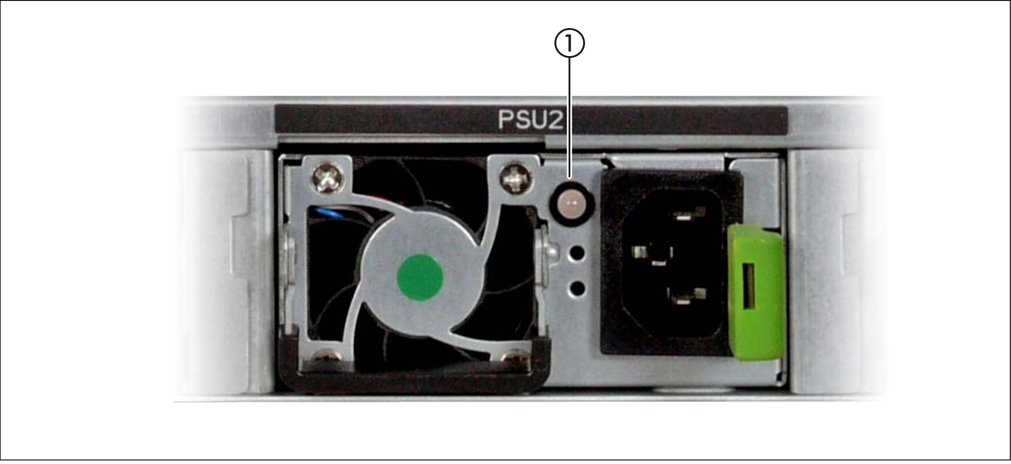
Figure 7: Indicators on the power supply units
No. | Meaning |
1 | Power supply unit fault indicator and warning indicator
Call Customer Support. |
Assignment of the PCIe slots
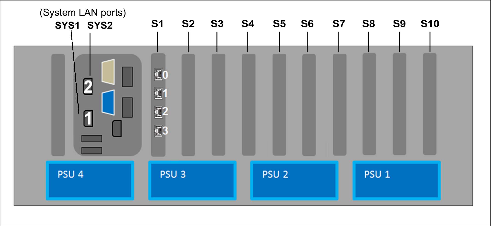
Figure 8: Principle of PCIe slot assignment at the rear of the device
The figure shows the PCIe slots of an SU300 (SU300 M2):
S1 is equipped with a 4-port LAN controller.
In the figure, slots S2 through S10 are not equipped.
Depending on the customer's wishes, the slots can be equipped with FibreChannel, LAN or (RAID) SAS controllers.
On models with mono processors (10A to 10F), only the PCIe-Slots S1 to S4 are available. The slots S5 through S10 can only be used with larger configuration.
They can optionally be upgraded with two further processor chips without changing the BS2000 performance so that additional Linux/Windows guest systems can be operated on XenVM and the full number of PCIe slots is also available.