Rear of the AU47 M3
Global error indicator and CSS indicator
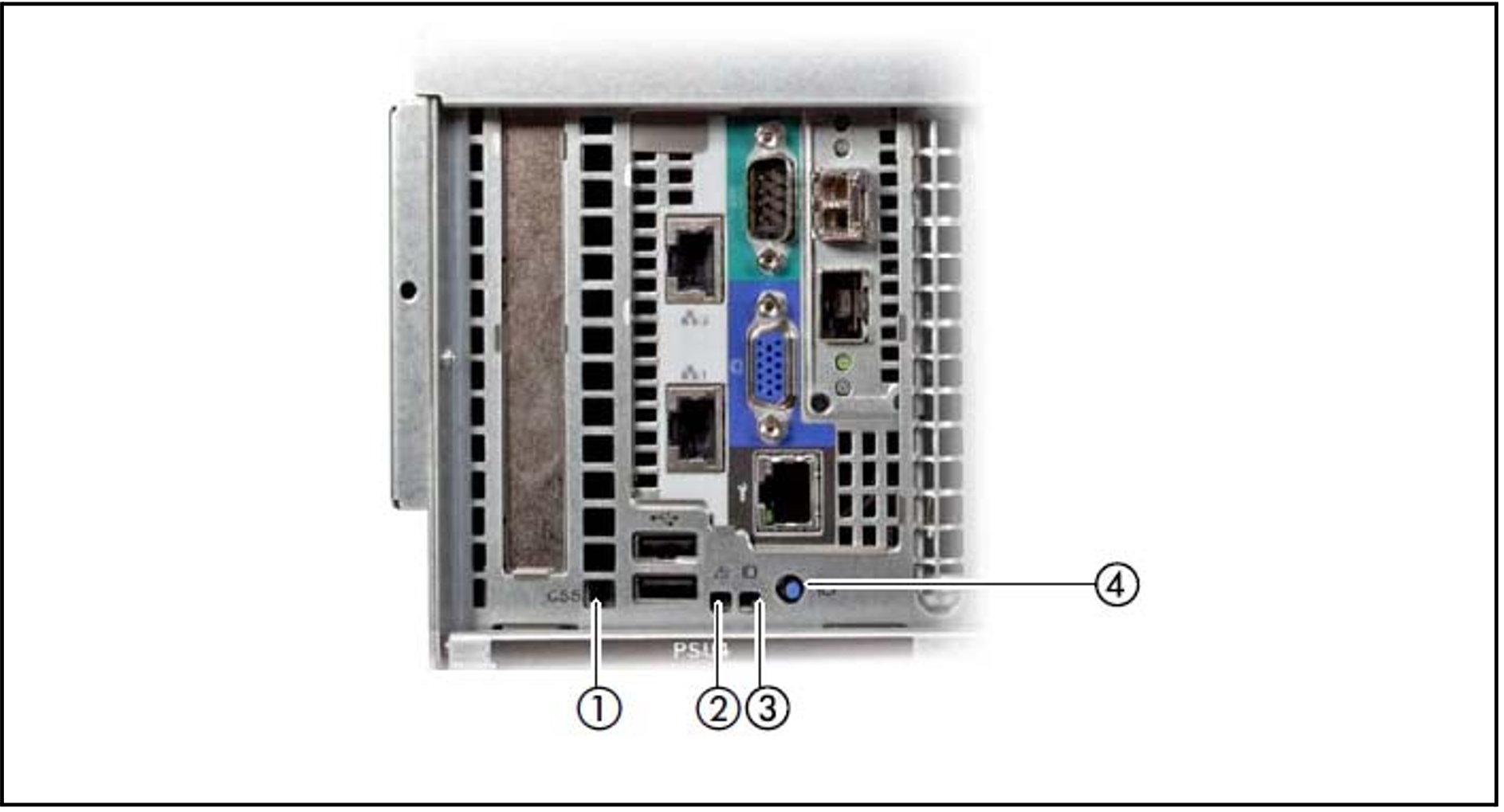
Figure 7: Global error indicator and CSS indicator, ID button and ID indicator
No. | Meaning |
1 | CSS indicator (yellow)
If the event is still acute after the Application Unit has been switched on/off, the indicator is activated after the restart. |
2 | Global error indicator (yellow)
If the event is still acute after a power failure, the indicator is activated after the restart. |
3 | ID indicator (blue)
The ID indicator can also be activated via the ServerView Operations Manager and the iRMC Web GUI, and the status can be reported to the ServerView Operations Manager and the iRMC. |
4 | ID button |
LAN ports
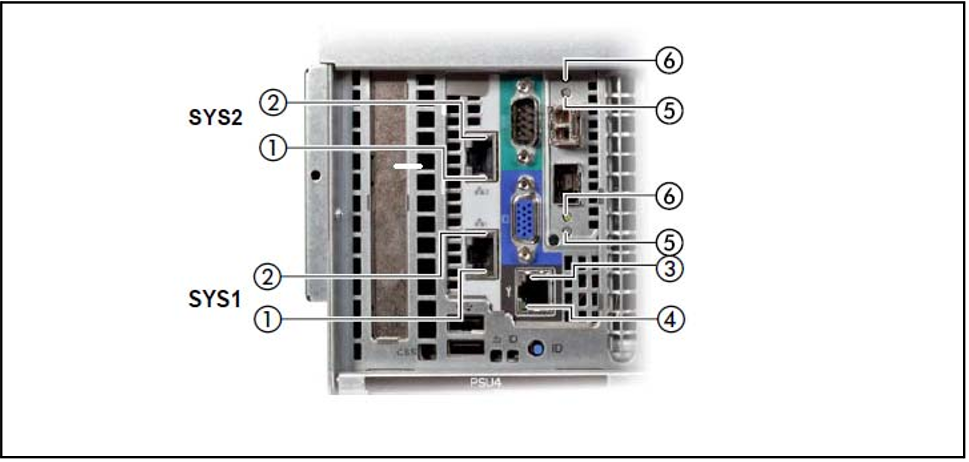
Figure 8: LAN ports on the Application Unit
No. | Meaning |
1 | LAN link/transfer
|
2 | LAN speed
|
3 | LAN speed (unused port) |
4 | LAN link/transfer (unused port) |
5 | LAN speed (unused port) |
6 | LAN link/transfer (unused port) |
The MAC addresses entered on the green ID card refer to LAN #1 (SYS1) and #2 (SYS2).
The MAC addresses of LAN ports #3 (not used) and #4 (not used) are then the next two MAC addresses in ascending order. The green ID card is located on the front of the Application Unit, see item 1 in figure 1/2.
Indicators on the power supply units
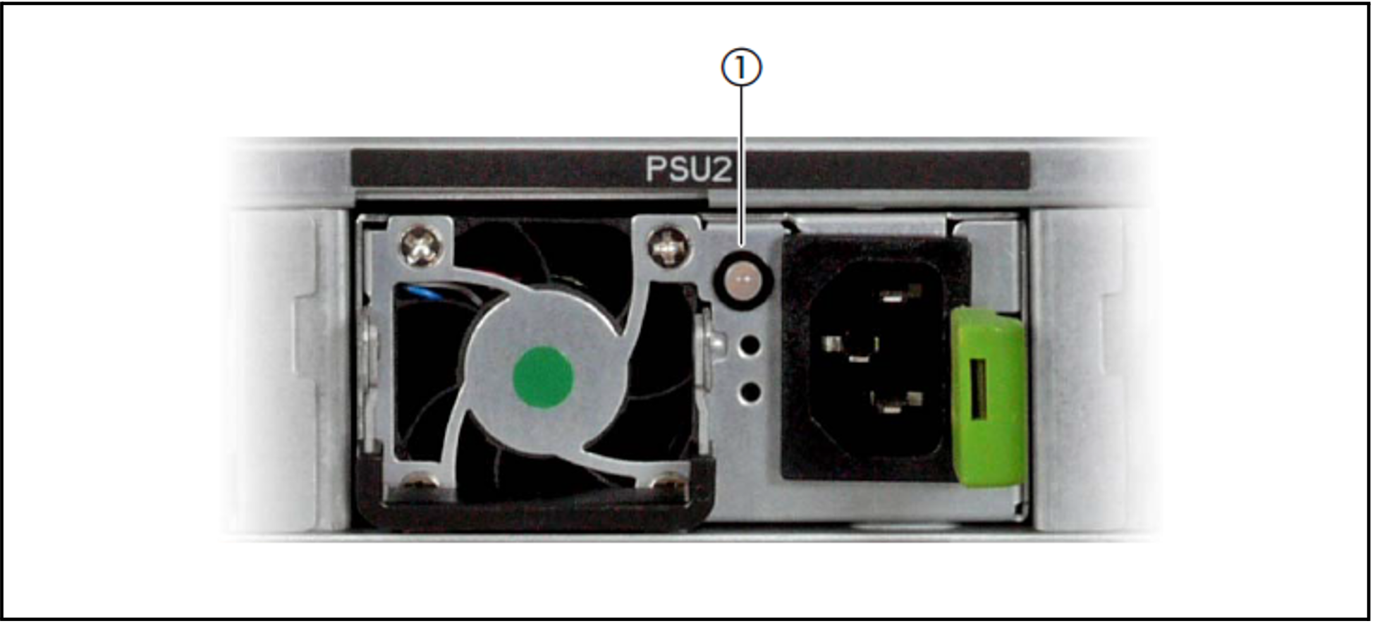
Figure 9: Indicators on the power supply units
No. | Meaning |
1 | Power supply unit fault indicator and warning indicator:
Call Customer Support. |
Assignment of the PCIe slots System LAN port
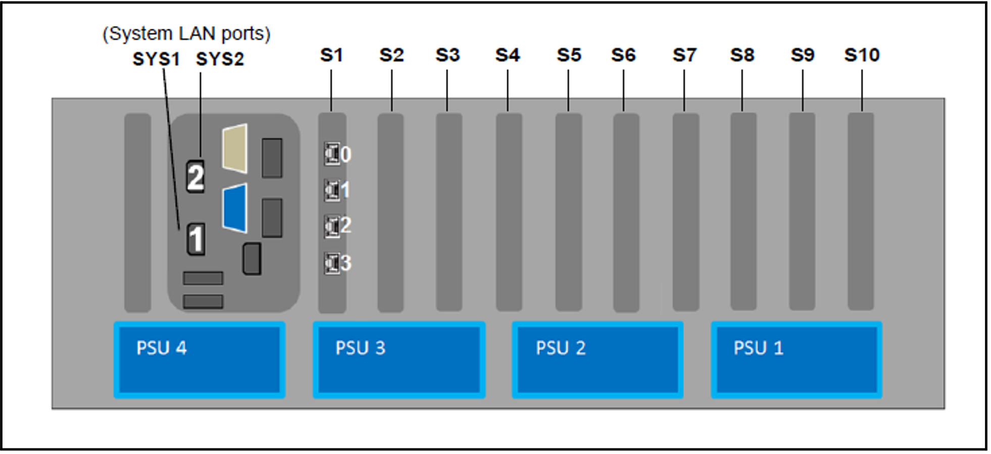
Figure 10: Principle of PCIe slot assignment at the rear of the device (AU47 M3)
The figure shows the PCIe slots of the AU:
S1 is equipped with a 4-port LAN controller.
Slots S2 through S10 are not equipped in the figure.
Rear of the AU47 M5
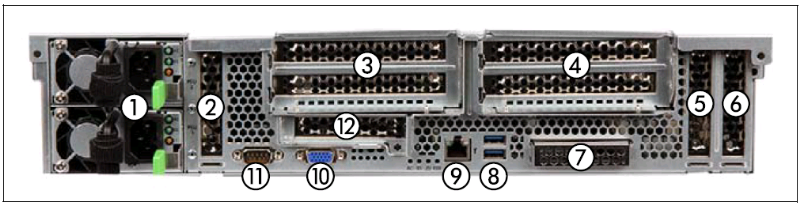
Figure 11: AU47 M5 (rear)
| No. | Meaning |
|---|---|
| 1 | Power cord connections |
| 2 | PCI slot 8 (low profile) |
| 3 | PCI slot 7 (top), PCI slot 6 (bottom) |
4 | PCI slot 4 (top), PCI slot 3 (bottom) |
| 5 | PCI slot 2 (low profile) |
| 6 | PCI slot 1 (low profile) |
| 7 | Onboard LAN (SYS1/SYS2 connections) |
| 8 | 2x USB 3.0 ports |
| 9 | iRMC Management LAN (SYS0) |
| 10 | VGA connection (to KVM adapter) |
| 11 | Serial connection (normally unused) |
| 12 | PCI slot 5 (low profile) |
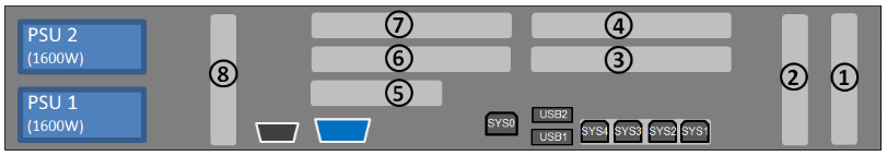
Figure 12: Principle of PCIe slot assignment at the rear of the device (AU47 M5)