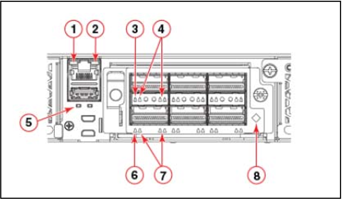
The Brocade ICX 7750-48F switch has the following LEDs on the rear panel:
Two Management port status LEDs
Two stack control path port LEDs
Expansion module LEDs:
One Power LED bicolor status LED (green and amber)
Four bicolor status LEDs (green and amber) for each of the six QSFP+ ports that indicate the status of the ports in 40 GbE mode and 4x10 GbE breakout mode.
Power supply LEDs: One status LED on each installed PSU (Power Supply Unit)
Fan tray LEDs: One status LED on each installed fan tray
The figure 14 shows the LEDs on the rear panel of the Brocade ICX 7750-48F.
Figure 14: Net Unit (ICX 7750-48F) LEDs (rear panel)
Explanation:
1 | Management port 10/100 Mbps link/activity LEDs |
2 | Management port 1000 Mbps link/activity LEDs |
3 | Upper slot 40 GbE mode link/activity LED or 10 GbE mode lane 1 link/activity LEDs |
4 | Lower slot 10 GbE mode lanes 2, 3, and 4 link/activity LEDs |
5 | UP port (left) and DN port (right) link status LEDs |
6 | Lower slot 40 GbE mode link/activity LED or 10 GbE mode lane 1 link/activity LEDs |
7 | Lower slot 10 GbE mode lanes 2, 3, and 4 link/activity LEDs |
8 | Expansion module power LED |

