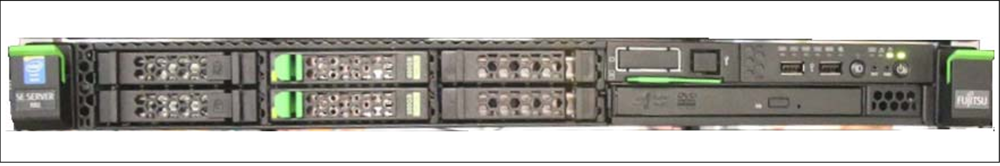
Figure 14: Management Unit (MU) - front of an MU M1
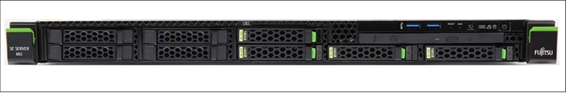
Figure 15: Management Unit (MU) - front of an MU M2
Indicators on the front panel of MU M1
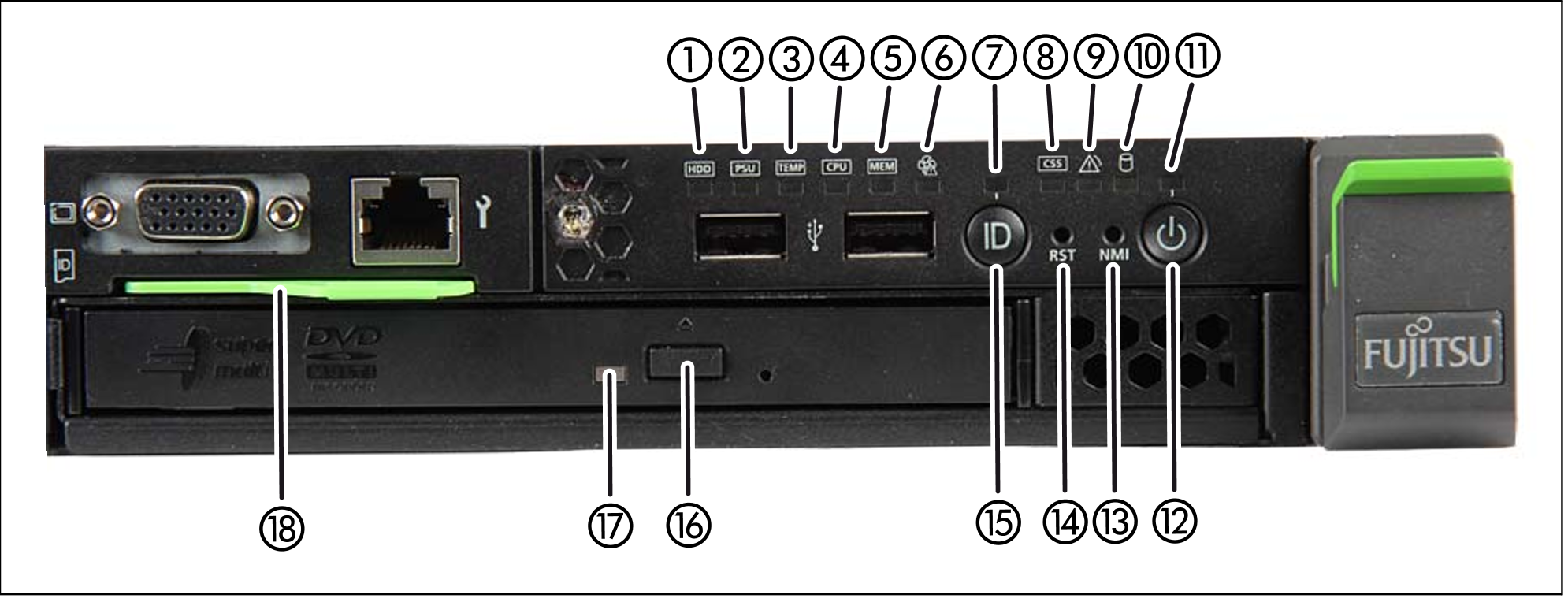
Figure 16: MU M1 (front panel)
1 | HDD fault indicator |
2 | Power supply fault indicator |
3 | Temperature fault indicator |
4 | CPU fault indicator (notify Customer Support) |
5 | Storage fault indicator (notify Customer Support) |
6 | Fan fault indicator (notify Customer Support) |
7 | ID indicator |
8 | CSS indicator (notify Customer Support) |
9 | Global error indicator (notify Customer Support) |
10 | HDD activity indicator |
11 | Status indicator |
12 | On/Off button |
13 | NMI button (for Customer Support only) |
14 | Reset button (for Customer Support only) |
15 | ID button |
16 | Open/close optical drive |
17 | Optical drive activity indicator |
18 | ID card (green) |
Indicators on the front panel of MU M2
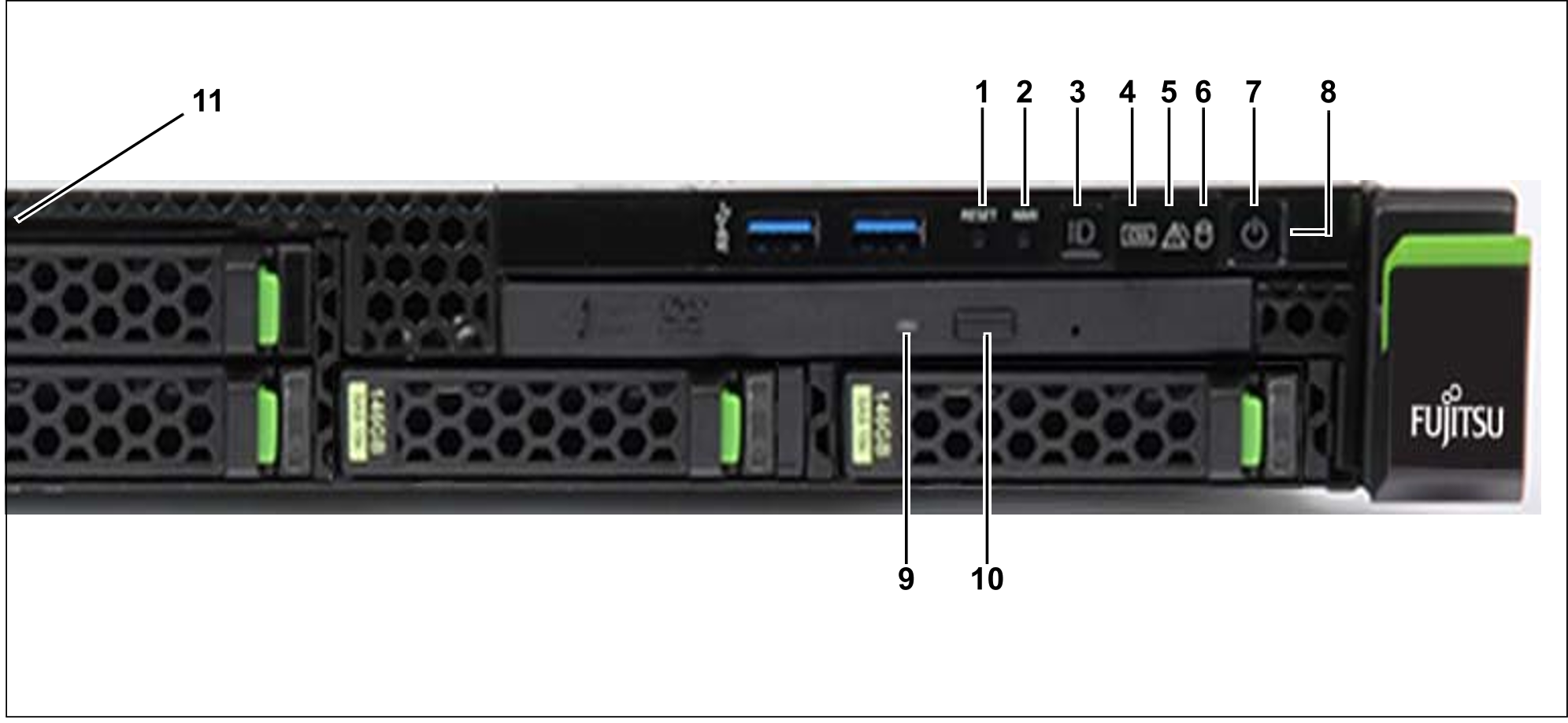
Figure 17: MU M2 (front panel)
1 | Reset button (for Customer Support only) |
2 | NMI button (for Customer Support only) |
3 | ID button / ID indicator |
4 | CSS indicator (orange); notify Customer Support |
5 | Global error indicator (orange); notify Customer Support |
6 | HDD/SSD activity indicator |
7 | On/Off button / Status indicator |
8 | Status indicator (power cable connected); next to the On/Off switch |
9 | Optical drive activity indicator |
10 | Open/close optical drive |
11 | ID card (green); further left, above HDD module |
The DVD-RW drive is used by Customer Support to install and update the M2000 software.
Use of the USB interfaces is reserved for Customer Support.
You can pull the ID card out and push it in again as far as it will go. The ID card contains various system information, e.g. product name, serial number, MAC addresses and DNS name.
Indicators on the front panel of MU M3
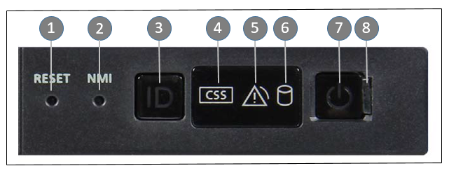
Figure 18: Indicators and control elements on the front panel of MU M3
Pos. | Label | Key / Display | Function | Status |
1 | RESET | Reset key | System restart (for Customer Support only) | |
2 | NMI | NMI key | For Customer Support only | |
3 | ID | ID button / ID indicator | Identifies the ID display on the front panel and at the I/O panel for an easier server identification. | blue on |
4 |
| CSS display | Notify Customer Support if on or flashing | off / orange / orange flashing |
5 |
| Global error display | Notify Customer Support if on or flashing | off / orange / orange flashing |
6 |
| HDD/SSD activity indicator | Data access running | green flashing |
7 |
| On/Off button | Switch on server: Off / Server switched on / BMC firmware starting after connection to power grid | off / green on / green flashing slowly |
8 |
| Status indicator (power cable connected) | Server switched off and connected to power grid (stand-by mode) / Server switched off and not connected to power grid or switched on and normal operation | green on / off |