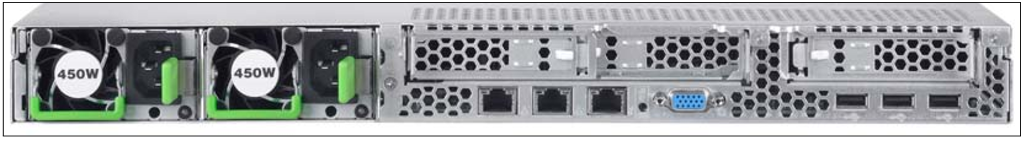
Figure 20: Management Unit (MU) - rear of an MU M1
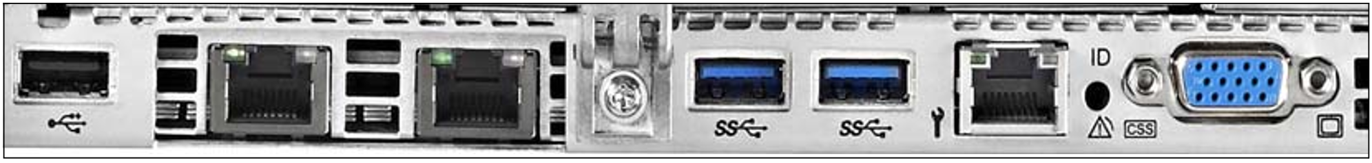
Figure 21: Management Unit (MU) - rear of an MU M2
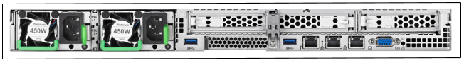
Figure 22: Management Unit (MU) - rear of an MU M3
Figures 20, 21 and 22 show the rear of an MU M1, MU M2 and MU M3 with PCIe slots which are not equipped.
ID/CSS/Global error indicator
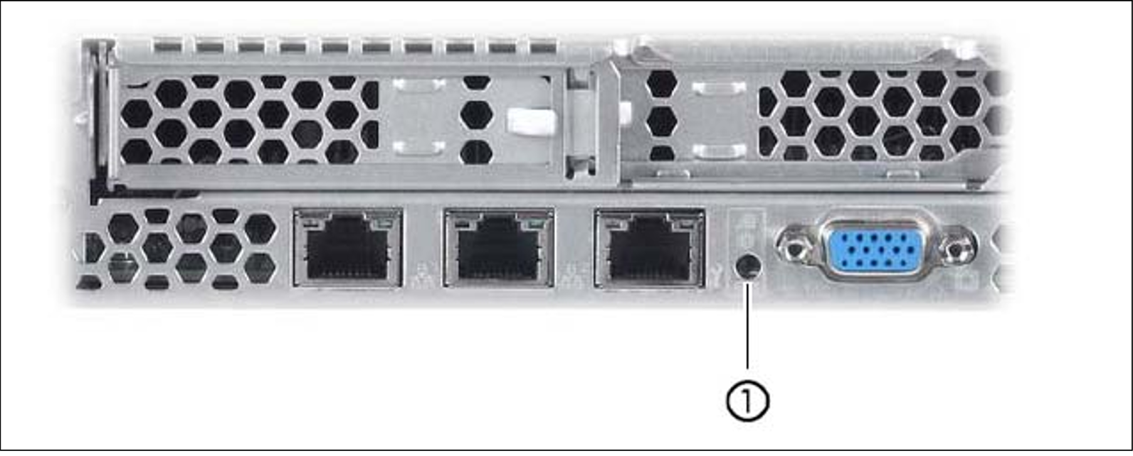
Figure 23: ID/CSS/Global error indicator (MU M1)
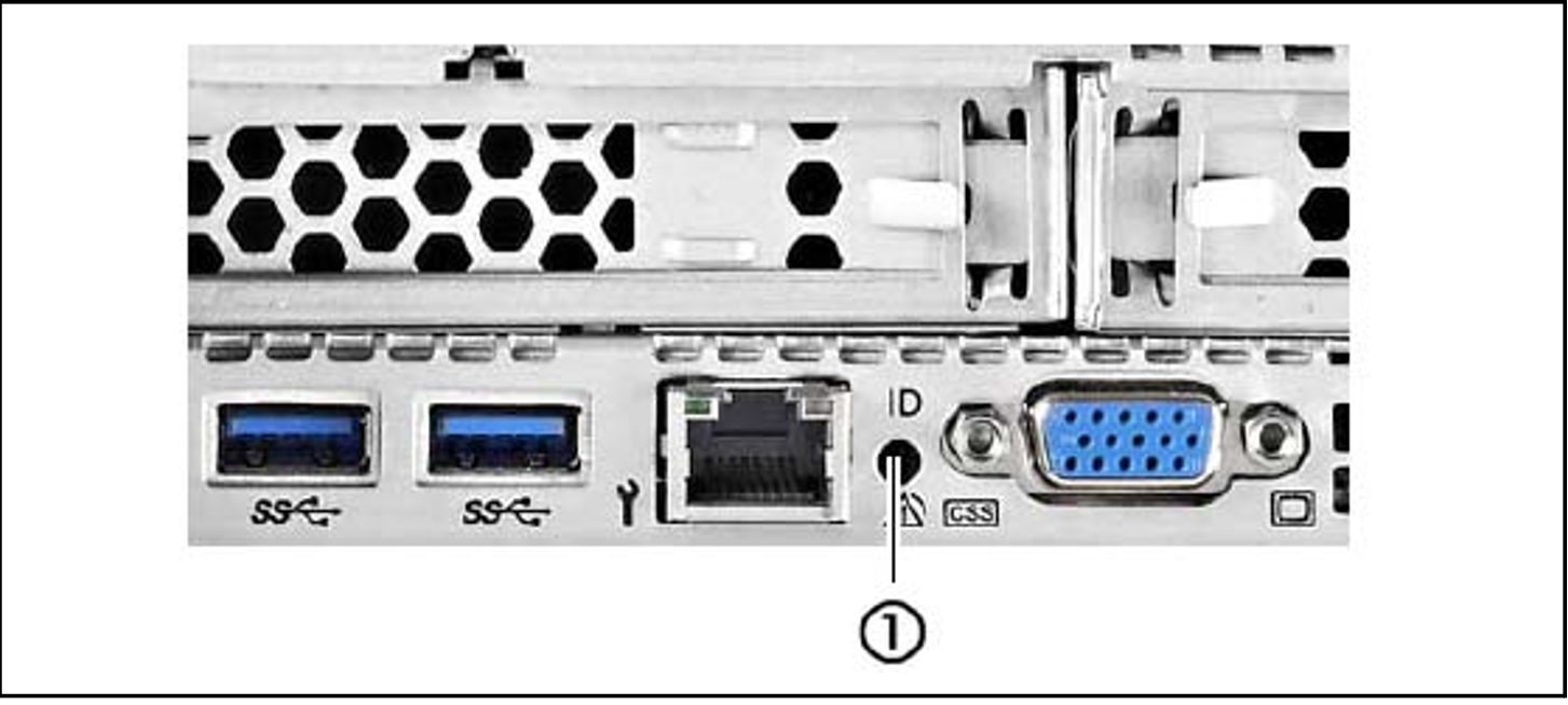
Figure 24: ID/CSS/Global error indicator (MU M2)
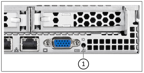
Figure 25: ID/CSS/Global error indicator (MU M3)
1 | ID/CSS/Global error indicator |
ID | ID indicator (blue) Lights up blue when the MU has been selected by pressing the ID button. To The ID indicator can also be activated via the ServerView Operations Manager and the iRMC S4/S5 web interface, and the status can be reported to the ServerView Operations Manager and the iRMC S4/S5. |
CSS | CSS and Global error indicator (yellow/orange) |
 | Generally, the states of these indicators have the following meanings:
Irrespective of the color, when an indicator lights up or flashes this indicates an error event. Please notify customer support. |
LAN indicators
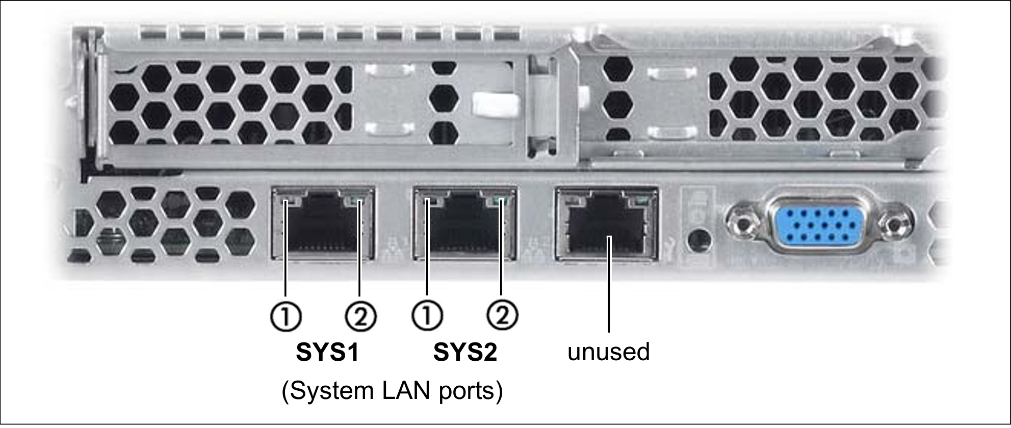
Figure 26: LAN indicators (MU M1)
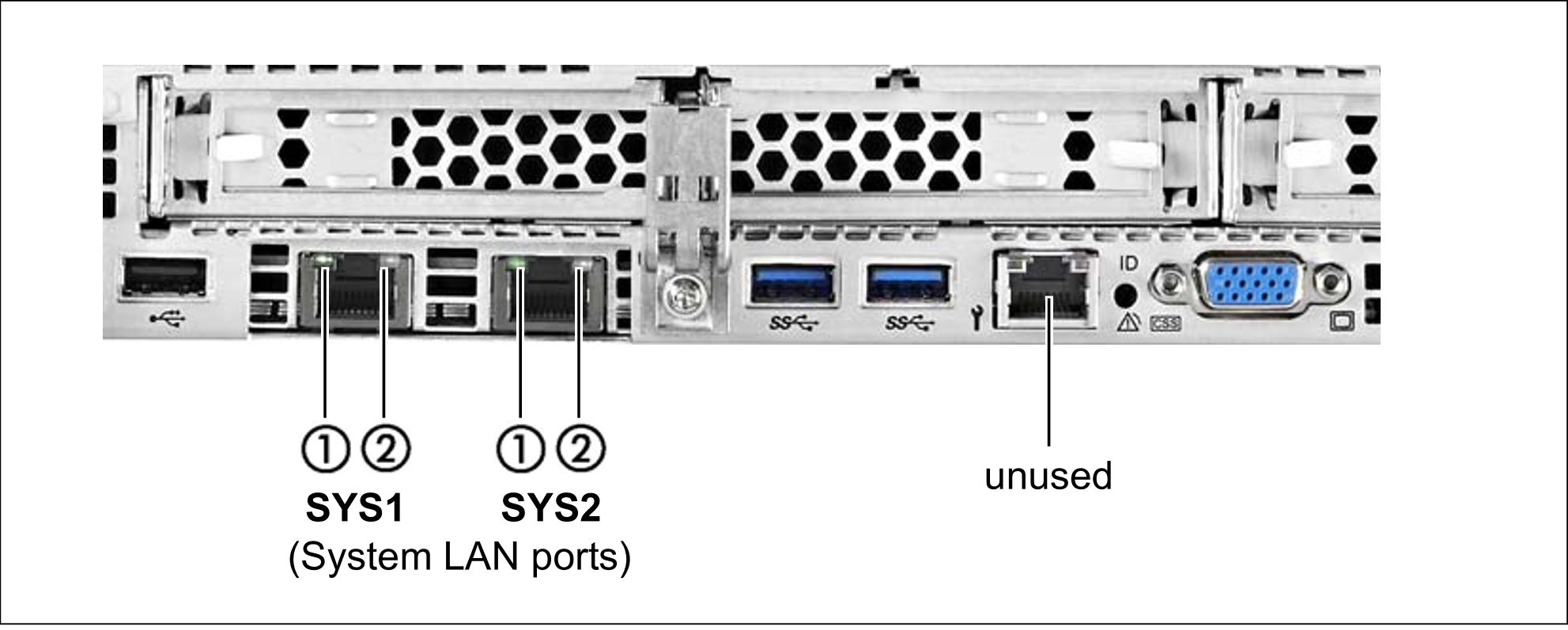
Figure 27: LAN indicators (MU M2)
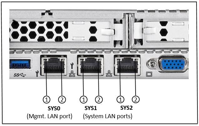
Figure 28: LAN indicators (MU M3)
1 | LAN speed | Lights up green for a LAN transfer rate of 1 Gbps. |
2 | LAN connection/transfer | Lights up green if a LAN connection exists. |
Indicator on hot-plug power supply unit
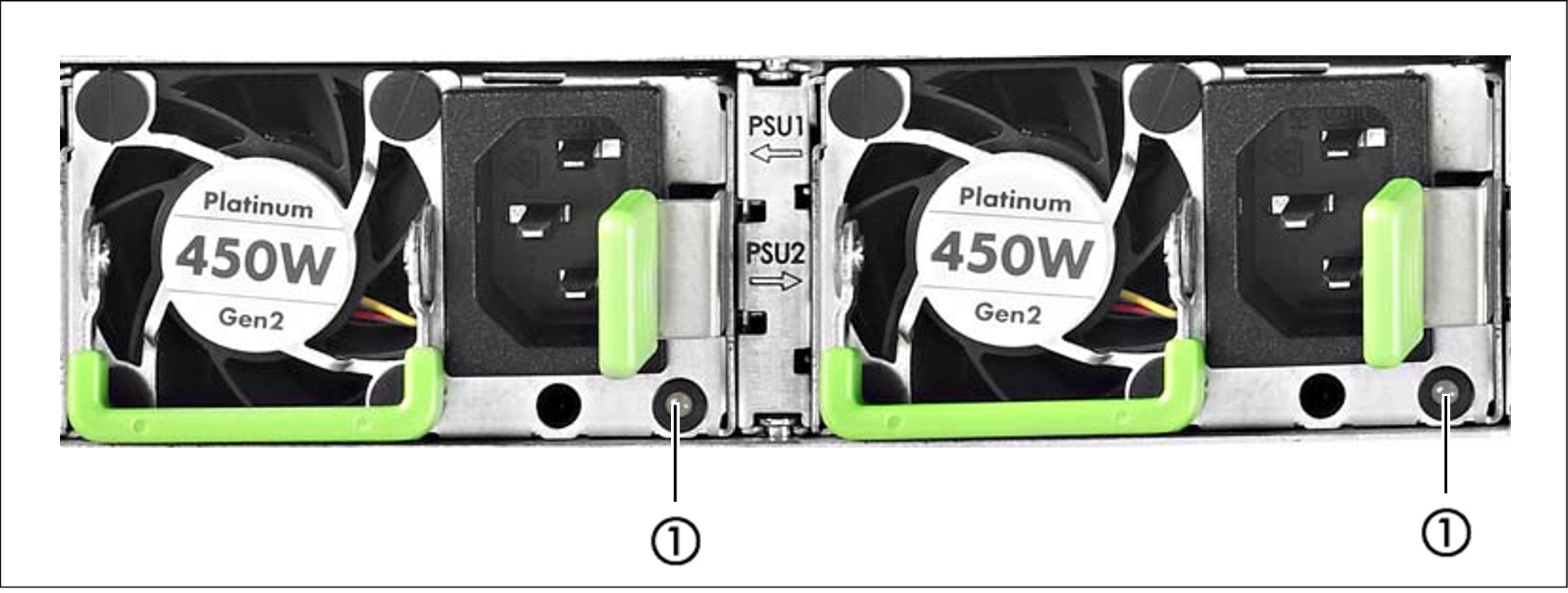
Figure 29: Indicator on hot-plug power supply unit
1 |
|
1) The following events are detected as predictable errors:
The temperature is very high.
The power consumption is very high.
The strength of current is very high.
The fan speed is very low.
In each of these cases please notify Customer Support.
Assignment of the PCIe slots
The assignment of the PCIe slots differs between MU M1, MU M2 and MU M3.
PCIe slot assignment on an MU M1
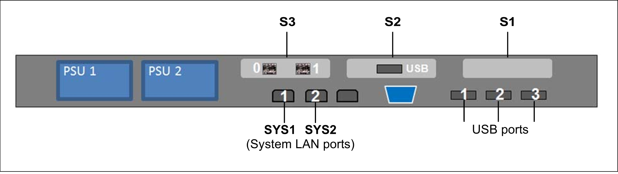
Figure 30: Principle of PCIe slot assignment at the rear of the device (MU M1)
The figure shows the PCIe slots of the MU M1 on an SE700. On the various model series of the SE server, the PCIe slots of an MU M1 are assigned as follows:
PCIe slot | SE700 | SE500 | SE300 |
S1 | not assigned | not assigned | not assigned |
S2 | USB card | USB card | not assigned |
S3 | FibreChannel card | FibreChannel card | not assigned |
Table 2: PCIe slot assignment on an MU M1
The MU M1 can be equipped with a second FibreChannel card in the free PCIe slot S1. Accordingly, two more ports are available for the ROBAR connection and cluster functionality.
PCIe slot assignment on the MU M2
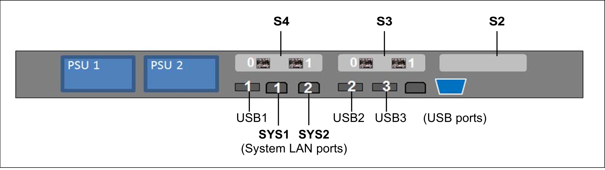
Figure 31: Principle of PCIe slot assignment at the rear of the device (MU M2)
The figure shows the PCIe slots of the MU M2 on an SE700B. On the various model series of the SE server, the PCIe slots of an MU M2 are assigned as follows:
PCIe slot | SE700B | SE500B | SE300B |
S2 | not assigned | not assigned | not assigned |
S3 | FibreChannel card | FibreChannel card | not assigned |
S4 | FibreChannel card | FibreChannel card | not assigned |
Table 3: PCIe slot assignment on an MU M2
The MU M2 can be equipped with another FibreChannel card in the free PCIe slot S2. Accordingly, two more ports are available for the ROBAR connection and cluster functionality.
PCIe slot assignment on the MU M3
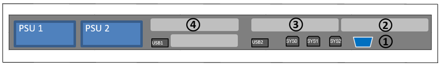
Figure 32: Principle of PCIe slot assignment at the rear of the device (MU M3)
The figure shows the PCIe slots of the MU M3 on an SE710. On the various model series of the SE server, the PCIe slots of an MU M3 are assigned as follows:
| PCIe slot | SE710 | SE310 |
|---|---|---|
| S2 | FibreChannel card | optional FibreChannel card (→ CRD) |
| S3 | optional FibreChannel card (→ CRD) | optional FibreChannel card (→ CRD) |
| S4 | not assigned | not assigned |
Table 4: PCIe slot assignment on an MU M3
The MU M3 can be equipped with another FibreChannel card in the free PCIe slot S4. Accordingly, two more ports are available for the ROBAR connection and cluster functionality.