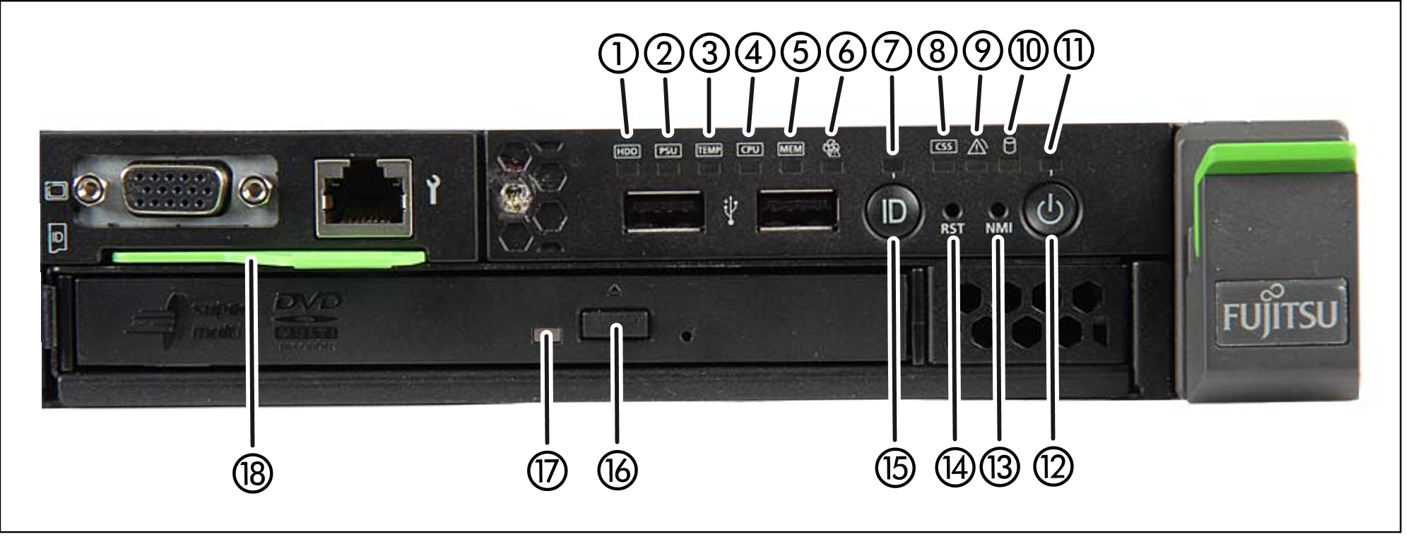
Figure 34: HNC M1 - front
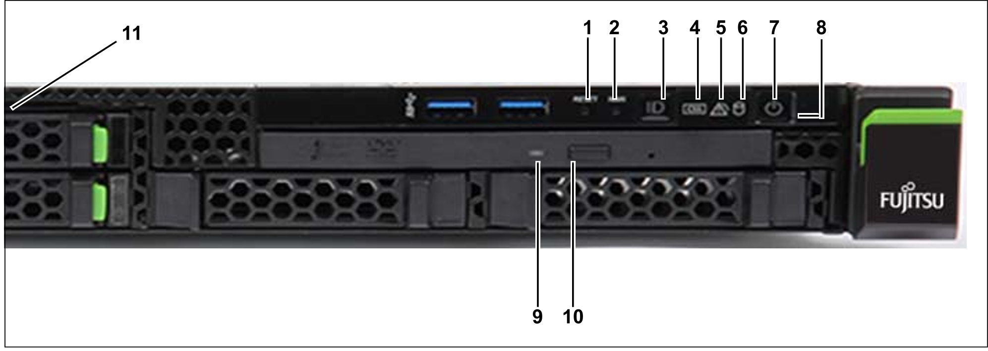
Figure 35: HNC M2/M3 - front
Indicators on the front panel of HNC M1
Figure 36: HNC M1 (front panel)
No. | Meaning |
1 | HDD/SDD error indicator |
2 | PSU fault indicator |
3 | Temperature fault indicator |
4 | CPU fault indicator (notify Customer Support) |
5 | Storage fault indicator (notify Customer Support) |
6 | Fan fault indicator (notify Customer Support) |
7 | ID indicator |
8 | CSS indicator (notify Customer Support) |
9 | Global error indicator (notify Customer Support) |
10 | HDD/SSD activity indicator |
11 | Status indicator |
12 | On/Off button |
13 | NMI button (for Customer Support only) |
14 | Reset button (for Customer Support only) |
15 | ID button |
16 | Open/close optical drive |
17 | Optical drive activity indicator |
18 | ID card (green) |
Indicators on the front panel of HNC M2/M3
Figure 37: HNC M2/M3 (front panel)
No. | Meaning |
1 | Reset button (for Customer Support only) |
2 | NMI button (for Customer Support only) |
3 | ID button / ID indicator |
4 | CSS indicator (orange); notify Customer Support |
5 | Global error indicator (orange); notify Customer Support |
6 | HDD/SSD activity indicator |
7 | On/Off button / Status indicator |
8 | Status indicator (power cable connected); next to the On/Off switch |
9 | Optical drive activity indicator |
10 | Open/close optical drive |
11 | ID card (green); further left, above HDD module |
Optical drive and USB interfaces
The DVD-RW drive is used by Customer Support to install and update the HNC software.
Use of the USB interfaces is reserved for Customer Support.


