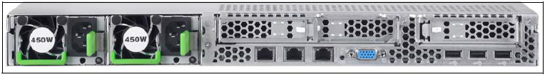
Figure 39: HNC M1 - rear
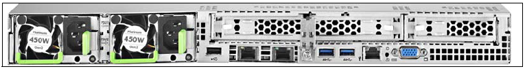
Figure 40: HNC M2 - rear
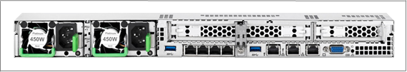
Figure 41: HNC M3 - rear
ID/CSS/Global error indicator
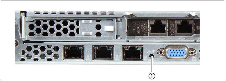
Figure 42: ID/CSS/Global error indicator (HNC M1)
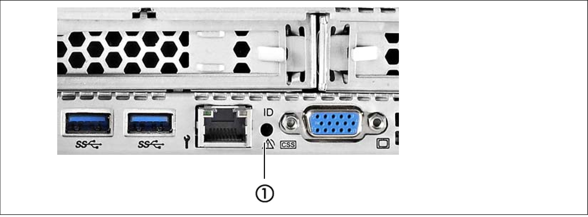
Figure 43: ID/CSS/Global error indicator (HNC M2)
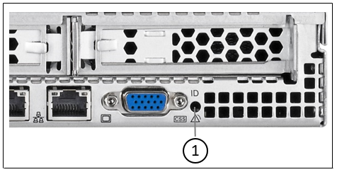
Figure 44: ID/CSS/Global error indicator (HNC M3)
No. | Meaning |
1 | ID/CSS/Global error indicator |
Element | Meaning |
ID | ID indicator (blue) Lights up blue when the HNC has been selected by pressing the ID button. To deactivate, press the button again. |
CSS | CSS and Global error indicator (yellow/orange) |
| Generally, the states of these indicators have the following meanings:
Irrespective of the color, when an indicator lights up or flashes this indicates an error event. Please notify customer support. |

LAN indicators
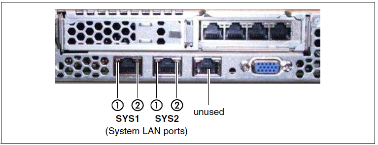
Figure 45: LAN indicators (HNC M1)
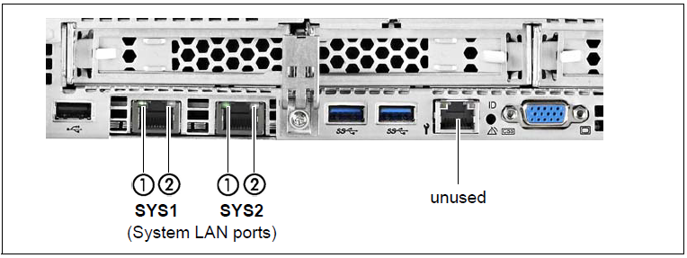
Figure 46: LAN indicators (HNC M2)
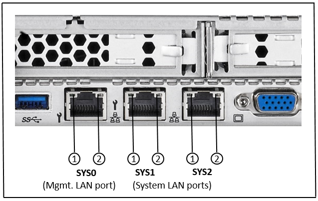
Figure 47: LAN indicators (HNC M3)
No. | Meaning |
1 | LAN activity indicator Lights up green if a LAN connection exists. |
2 | LAN speed indicator Lights up yellow for a LAN transfer rate of 1 Gbps. |
Indicator on hot-plug power supply unit
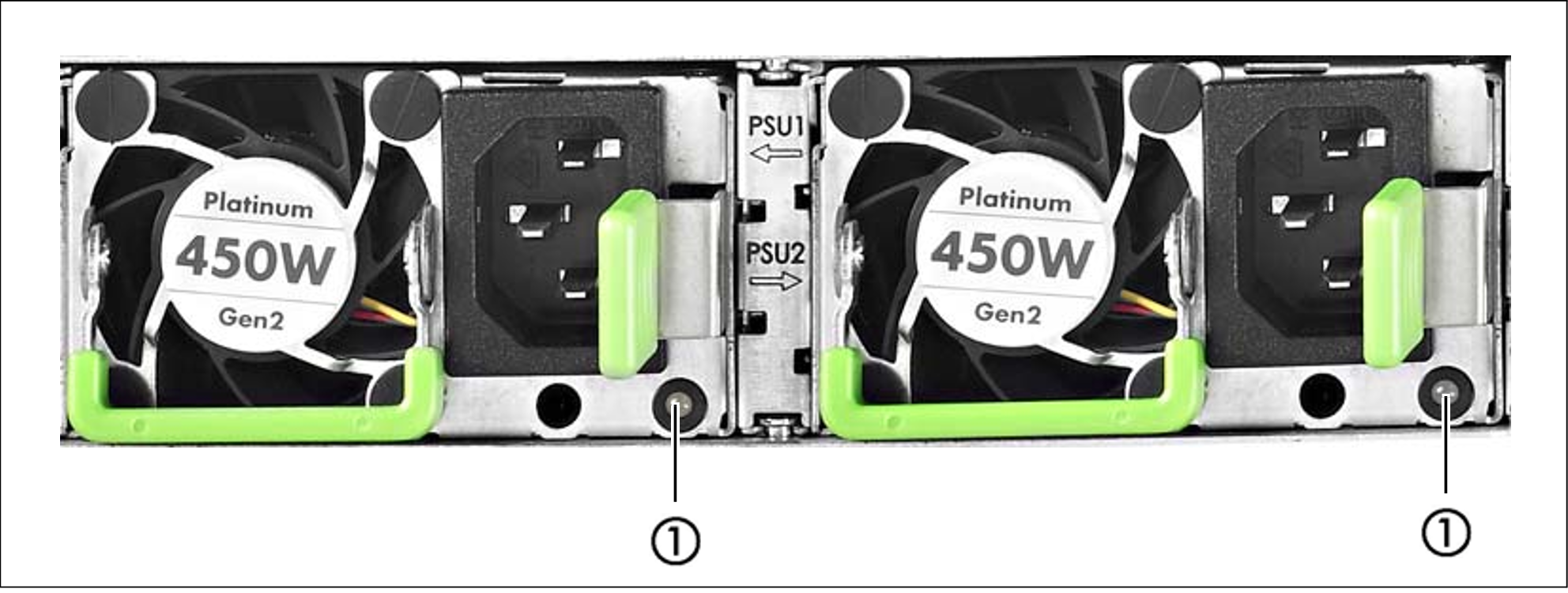
Figure 48: Indicator on hot-plug power supply unit
No. | Meaning |
1 | Indicator on hot-plug power supply unit (two colors) Flashes green when the HNC is switched off, but line voltage is present (standby mode). Lights up green when the HNC is switched on and functioning properly. Flashes orange when a predictable error has been detected, but the power supply unit is still running.1) Lights up orange when no line voltage is present or the power supply unit has failed. |
1) | The following events are detected as predictable errors:
In each of these cases please notify Customer Support. |
Assignment of the PCIe slots
The assignment of the PCIe slots differs for HNC M1, M2 and M3.
PCIe slot assignment of HNC M1
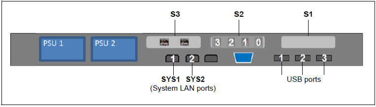
Figure 49: Principle of PCIe slot assignment at the rear of the device (HNC M1)
PCIe slot | Assignment |
S1 | Not assigned; an optical LAN card is optionally possible |
S2 | 4-port LAN card |
S3 | FibreChannel card |
Table 2: PCIe slot assignment on an HNC M1
PCIe slot assignment of HNC M2
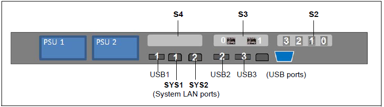
Figure 50: Principle of PCIe slot assignment at the rear of the device (HNC M2)
PCIe slot | Assignment |
S2 | 4-port LAN card |
S3 | FibreChannel card |
S4 | not assigned; an additional 4-port LAN card or a 10 GbE LAN card with 2 optical or RJ45 interfaces are optional |
Table 3: PCIe slot assignment on an HNC M2
PCIe slot assignment of HNC M3
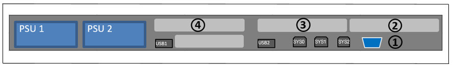
Figure 51: Principle of PCIe slot assignment at the rear of the device (HNC M3)
| PCIe slot | Assignment |
|---|---|
| 1 | SAS RAID controller for internal HDDs |
| 2 | optional 4-port LAN card (10 GBit) with RJ45 interfaces or 4-port LAN card (10 GBit) with optical interfaces |
| 3 | FibreChannel card |
| 4 | 4-port LAN card (10 GBit) with RJ45 interfaces |
Table 4: PCIe slot assignment on an HNC M3