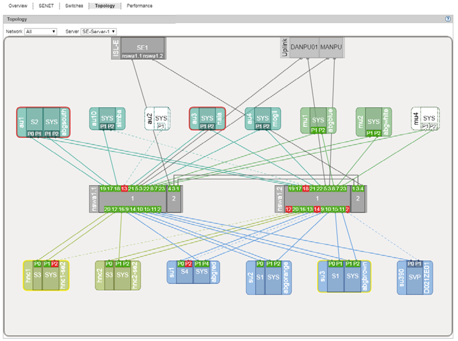
A graphical display of the network topology with all the network components and connections is displayed in the Topology tab.
> | Select Hardware -> IP networks, Topology tab. |
You can influence the display:
In the display of the topology you can have a selected network highlighted, i.e. this network is displayed normally and the components of all other IP networks are grayed out.
For a Management Cluster, you can select the SE server for which you want to display the topology, from the Server list. The default is the SE server of the local MU.
When you drag the mouse cursor over a network component, a tool tip displays detailed information on it (if available).
To view the relevant parts of the graphic, left-click and hold the graphic to drag it into the desired position.
In the case of AU PQ the chassis and system components IO Unit and Management Board are displayed together as one unit.
Further information can be found in the online help.

