Loading...
Select Version
&pagelevel(5)&pagelevel
Rear of the AU47 M5
Figure 6: AU47 M5 - rear
| No. | Meaning |
|---|---|
| 1 | Power cord connections |
| 2 | PCI slot 8 (low profile) |
| 3 | PCI slot 7 (top), PCI slot 6 (bottom) |
4 | PCI slot 4 (top), PCI slot 3 (bottom) |
| 5 | PCI slot 2 (low profile) |
| 6 | PCI slot 1 (low profile) |
| 7 | Onboard LAN (SYS1/SYS2 connections) |
| 8 | 2x USB 3.0 ports |
| 9 | iRMC Management LAN (SYS0) |
| 10 | VGA connection (to KVM adapter) |
| 11 | Serial connection (normally unused) |
| 12 | PCI slot 5 (low profile) |
Figure 7: AU47 M5 - principle of PCIe slot assignment at the rear of the device
Rear of the AU47 M6
Figure 8: AU47 M6 (rear)
| No. | Meaning |
|---|---|
| 1 | Power cord connections (one or two) |
| 2 | PCIe slots 10 and 11 (riser module) |
| 3 | PCIe slots 1 and 2 (riser module) |
| 4 | OCP module (optional) |
| 5 | Management LAN |
| 6 | Serial connection |
| 7 | 2x USB 3.0 ports |
| 8 | VGA connection (to KVM adapter) |
| 9 | PCIe slots 3 - 9 (low profile) |
Figure 9: AU47 M6 - Principle of PCIe slot assignment at the rear of the device
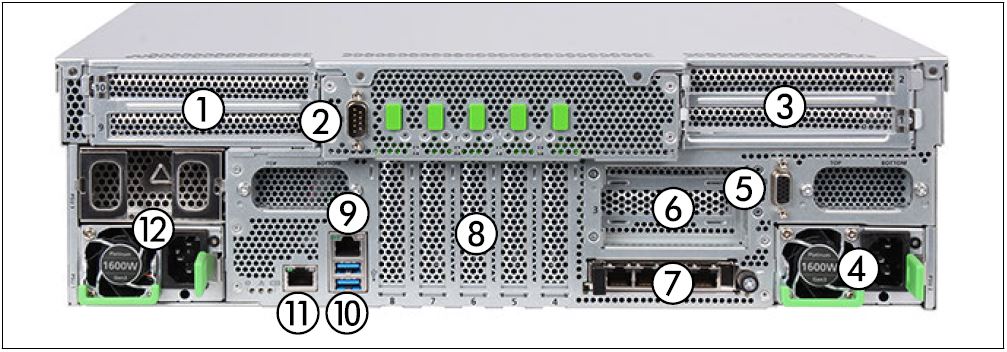
Rear of the AU47 M7
Figure 10: AU47 M7 (rear)
| No. | Meaning |
|---|---|
| 1 | PCIe slots 9 and 10 (riser module) |
| 2 | Serial connection |
| 3 | PCIe slots 1 and 2 (riser module) |
| 4 | Power cord connection |
| 5 | VGA connection (to KVM adapter) |
| 6 | PCIe slot 3 (LP riser module, optional) |
| 7 | OCP module (optional) |
| 8 | PCIe slots 4 - 8 |
| 9 | Shared LAN |
| 10 | 2x USB 3.1 ports |
| 11 | Management LAN |
| 12 | Power cord connections (up to two) |
Figure 11: AU47 M7 - Principle of PCIe slot assignment at the rear of the device


