The Highspeed Network Connect HNC connects an SU /390 with different IP networks. The connection to the networks can be set up via the direct port on the HNC or via the Net Unit. The Net Unit offers a number of networks in the SE server. The HNC is a component of the SE server and is operated and managed via the SE Manager, see the “Operation and Administration” manual [19].
With one HNC, network connections to the monitor system and all other guest systems can be established in VM2000 operation.
The data transfer between the various BS2000 guest systems of an SU /390 takes place in the HNC's internal network, without placing a load on private or customer networks.
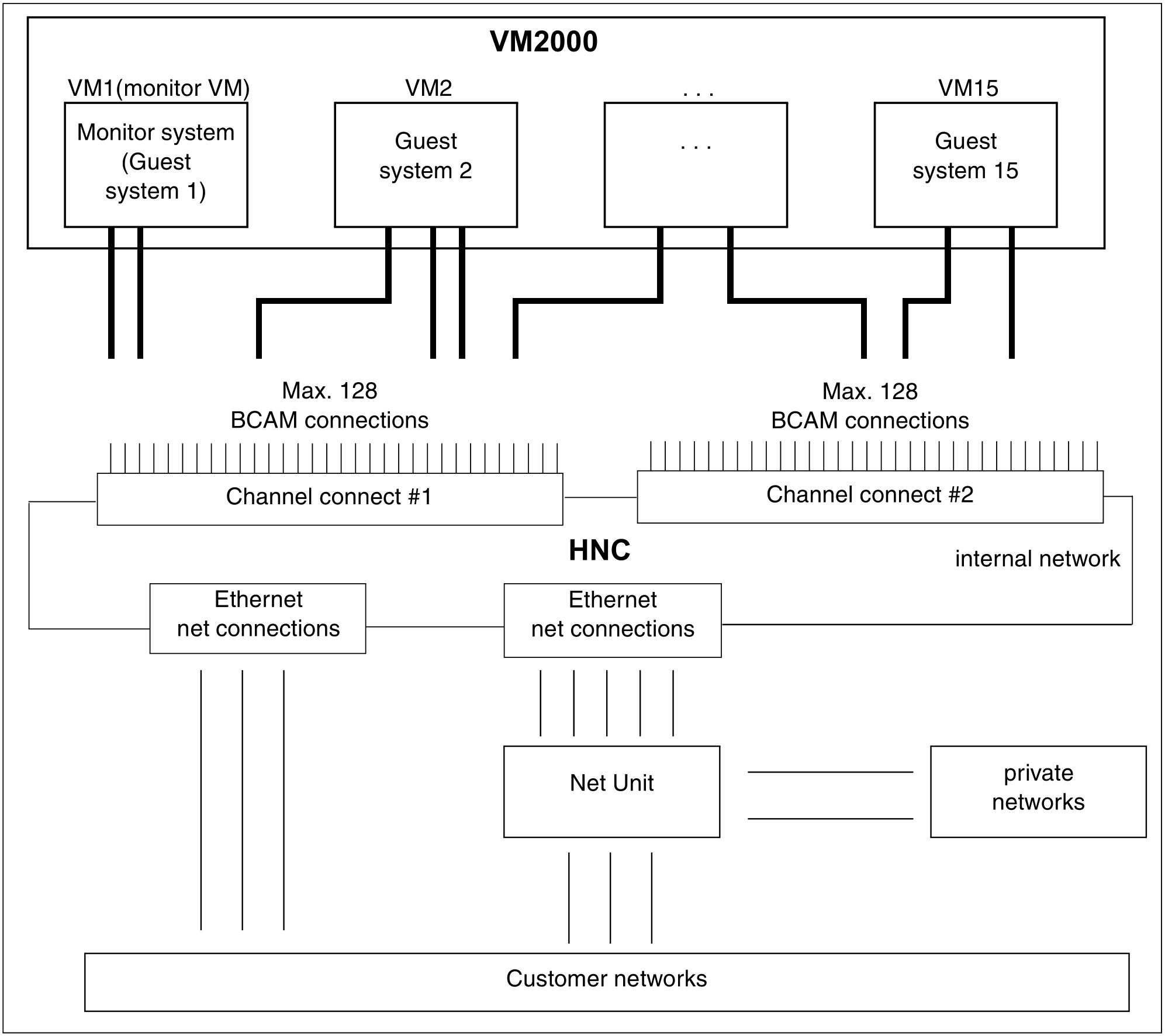
The HNC has 2 channel connects. On each channel connect, 128 BCAM network connections can be configured. Up to 4 HNCs can be connected on an SU /390, for example to set up redundant BCAM network connections. The HNC can be used to set up connections to different networks, e.g. client networks (DANPUx), SE private networks (DANPRxx) or the internal network (LOCLAN). For a successful connection, a BCAM line adapter must be defined for every guest system to the desired network and a corresponding address pair must be set up.
Specimen configuration
In the following example, such a configuration is assumed. The statements needed for installation, generation and assignment are shown.
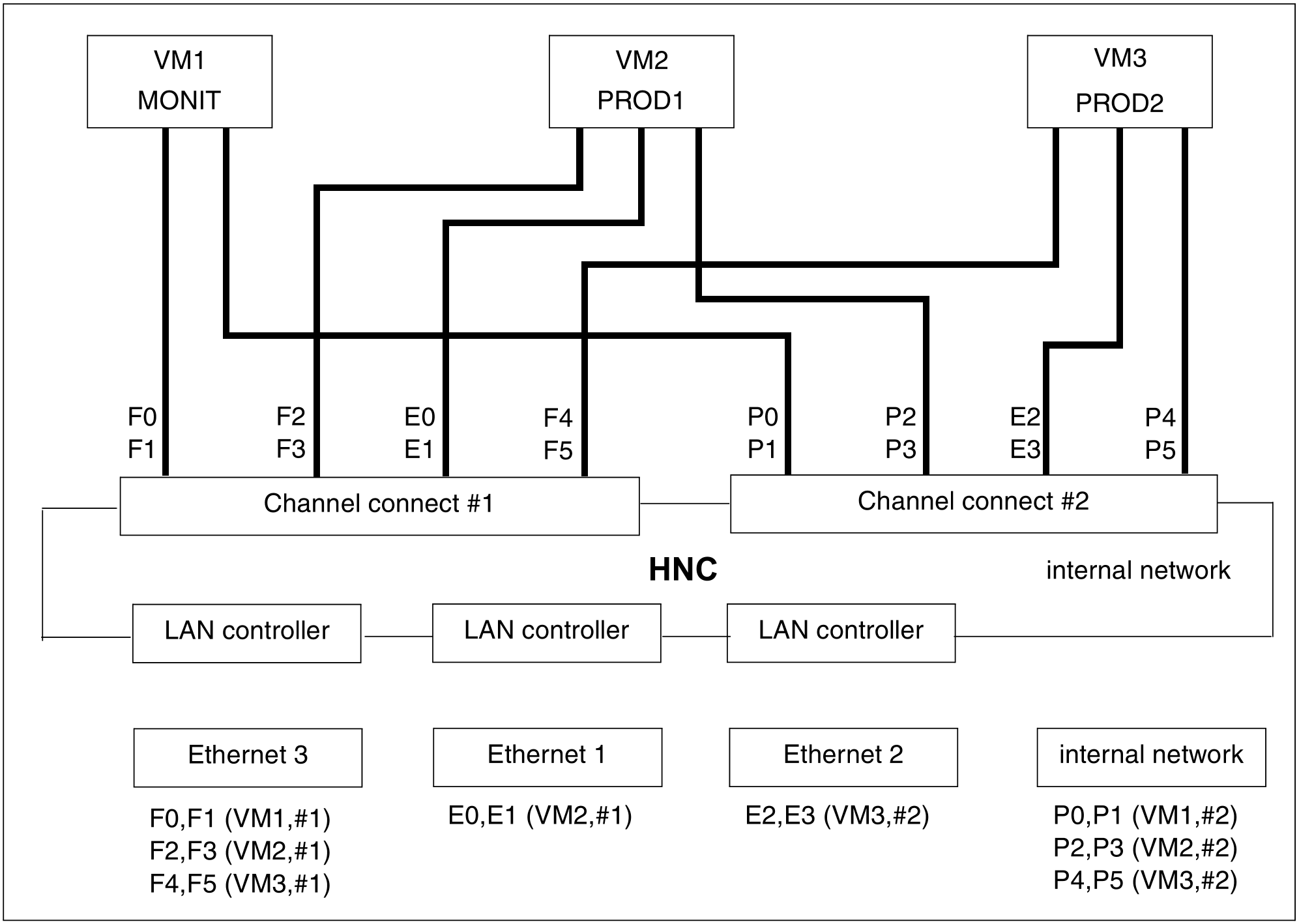
Three Ethernet networks and the internal network are installed. Three guest systems are running in VM2000 operation:
The monitor system (
MONITin VM1)Two production systems (
PROD1in VM2,PROD2in VM3)
An HNC is installed on two channels (channel connect #1 (C0) and #2 (C1)).
The assignment of the device address pairs to VMs, channel connects and networks can be seen from Figure 26.
Example
The device address pair F0,F1 on channel connect #1 (C0) belongs to a monitor VM (monitor system) BCAM line adapter: F0,F1,(VM1,#1).
Installation of the specimen configuration
The device address pairs for the BCAM line adapters (assigning the network and a network address in each case) are set up by Customer Service when the HNC is installed.
Generation of the specimen configuration
To generate the monitor system and the guest systems the appropriate generation statements must be specified for the channel connects and for the device addresses. In the above example, these must be specified as follows, when they are connected to, for example, channel K0 and K1:
* Channel connect #1 of HNC
   CTL C0,,(K0,0)
* Channel connect #2 of HNC
   CTL C1,,(K1,0)
* ETHERNET3 via channel connect #1 (C0)
   DVC F0,6D,A,00,(C0)
   DVC F1,6D,A,01,(C0)
   DVC F2,6D,A,02,(C0)
   DVC F3,6D,A,03,(C0)
   DVC F4,6D,A,04,(C0)
   DVC F5,6D,A,05,(C0)
* ETHERNET1 via channel connect #1 (C0)
   DVC E0,6D,A,06,(C0)
   DVC E1,6D,A,07,(C0)
* Internal network via channel connect #2 (C1)
   DVC P0,6D,A,00,(C1)
   DVC P1,6D,A,01,(C1)
   DVC P2,6D,A,0C,(C1)
   DVC P3,6D,A,03,(C1)
   DVC P4,6D,A,04,(C1)
   DVC P5,6D,A,05,(C1)
* ETHERNET2 via channel connect #2 (C1)
   DVC E2,6D,A,06,(C1)
   DVC E3,6D,A,07,(C1)
The BCAM line adapters to the device address pairs must be defined by using the appropriate BCAM statements (SOF definitions) (see the "BCAM" manual [8]).
Assigning the specimen configuration to VM2000
The information for setting up the monitor VM is stored in the configuration file of the monitor VM. While it is not essential, the network peripherals of the monitor VM should also be assigned via the configuration file, as they are then automatically available and ATTACHED when BCAM is started. The following statement is required for this in the above example:
/ADD-VM-DEVICES UNITS=(F0,F1,P2,P3),VM-ID=MONIT
In the above example, the following statements will be output for the network configuration of the production systems after setting up the VMs:
/ADD-VM-DEVICES UNITS=(F2,F3,E0,E1,P2,P3),VM-ID=PROD1/ADD-VM-DEVICES UNITS=(F4,F5,E2,E3,P4,P5),VM-ID=PROD2