In the Proxy Components tab in the property sheet Edit Properties of Local/Remote Proxy, you define the settings for the proxycomponents openUTM-LU62 Gateway and communication service.
These two proxy components are required for communication with CICS partners and must always run on the same computer. This does not have to be the computer on which the proxy is running.
The tab illustrated below already contains the necessary entries. When you perform initial set-up, further dialog boxes are displayed for the entry of the openUTM-LU62 Gateway and the communication server data.
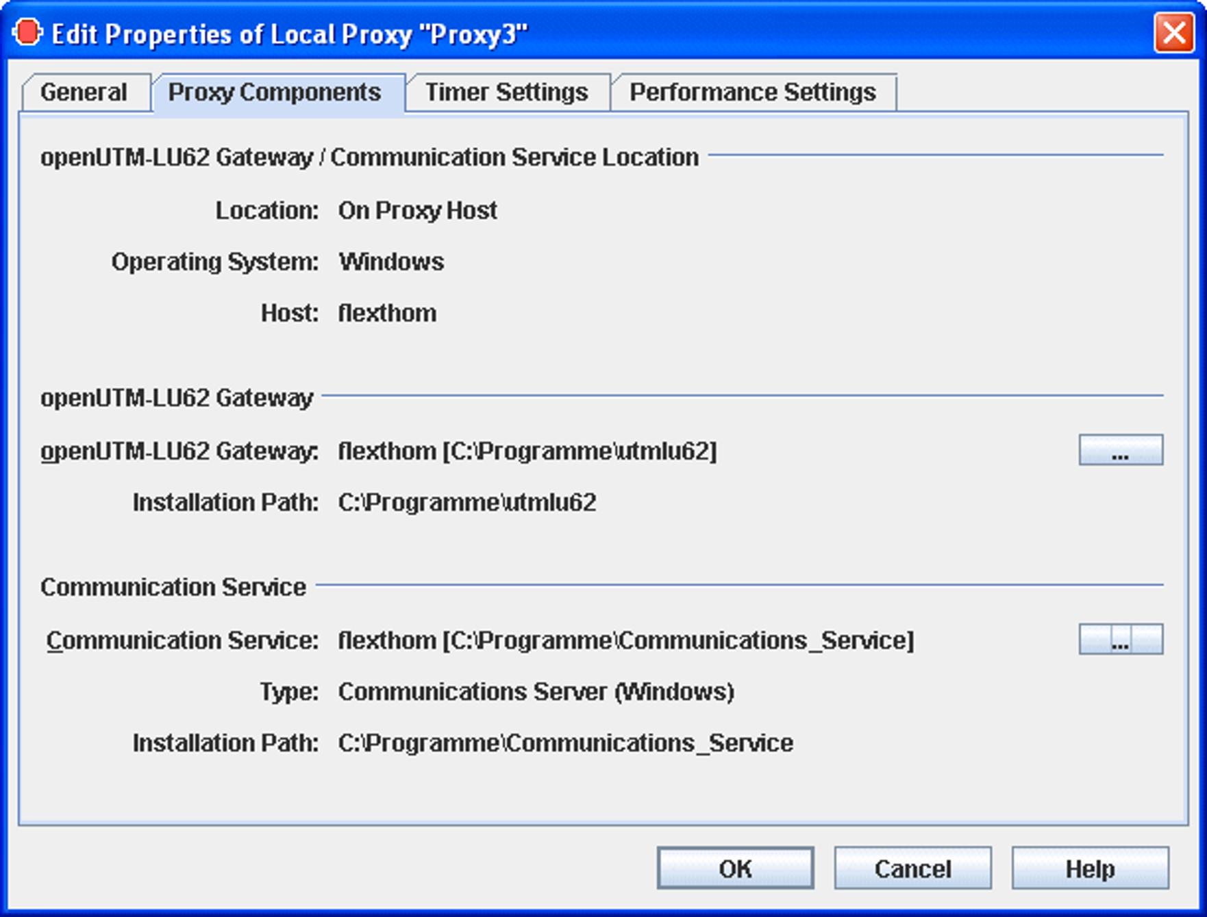
Figure 19: Description of the proxy components for CICS partners
openUTM-LU62 Gateway/Communication Service Location
Displays the location, the name and the operating system of the computer on which the proxy components openUTM-LU62-Gateway and communication service are running.
Location: On Proxy Host means: The same computer on which the proxy container is running.
Location: On Separate Host means: A different computer.
openUTM-LU62 Gateway
Specifies the computer and the directory in which the openUTM-LU62 Gateway is installed. To select a gateway, click the ... button to open the following sequence of dialog boxes:
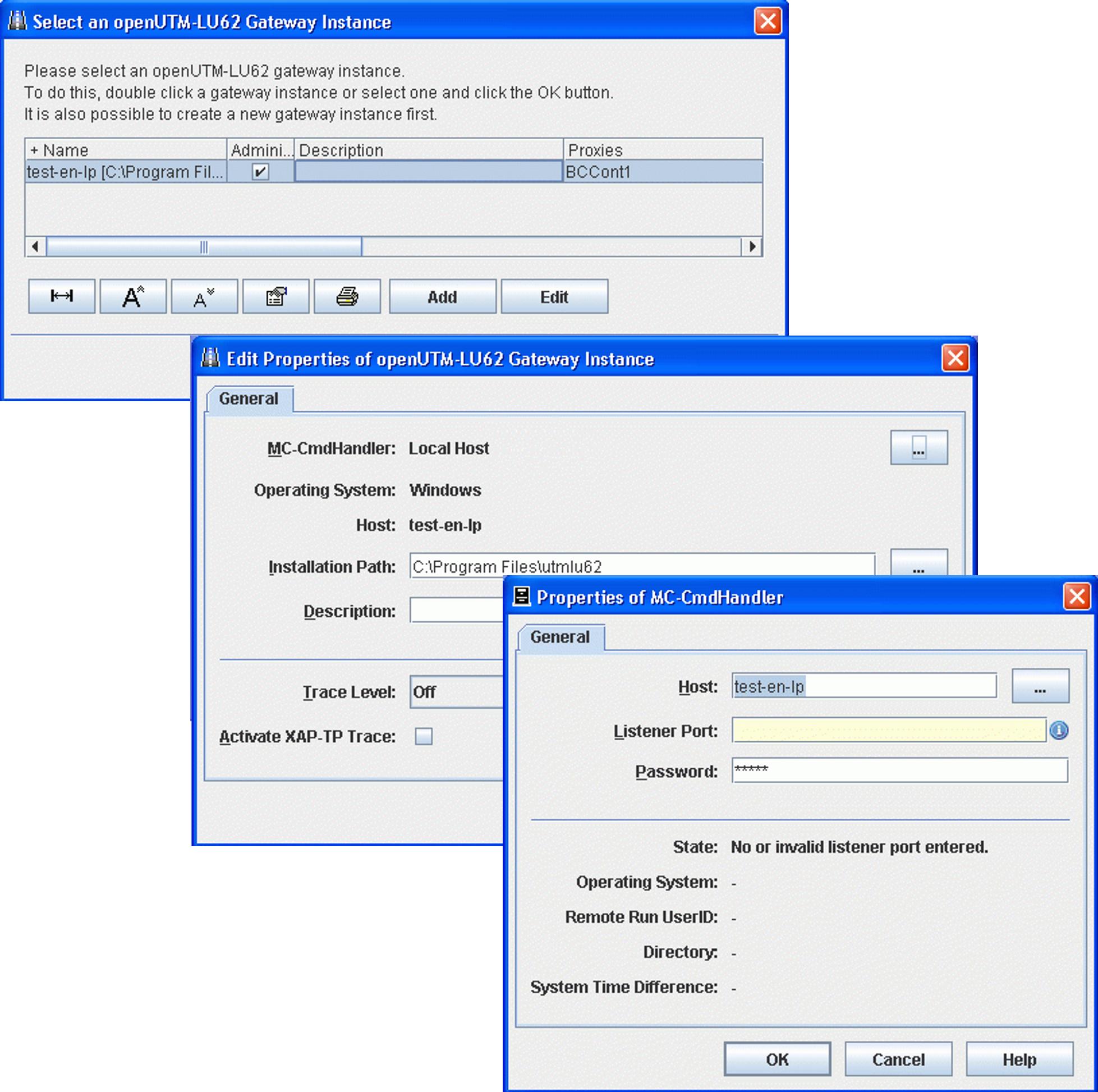
Figure 20: Configuring the openUTM-LU62 Gateway
The gateway instances that have already been configured are displayed in Select an openUTM-LU62 Gateway Instance. You can select an instance and click OK to assign this instance. You can click Edit to modify the properties of a selected instance.
Proceed as follows if you want to configure a new instance:
Click the Add button.
In Add openUTM-LU62 Gateway Instance, click the ... button under Select MC-CmdHandler to open the dialog Properties of MC-CmdHandler.
In Properties of MC-CmdHandler, enter the properties of the MC handler used to administer the components and click OK.
In Add openUTM-LU62 Gateway Instance, enter the installation path of the openUTM-LU62 Gateway and modify the traced properties if necessary. Click OK.
Communication Service
Specifies the computer, the type and the directory in which the communication service is installed. To select a communication service, click the ... button to open the following sequence of dialog boxes: Proceed in the same way as when entering an openUTM-LU62 Gateways:
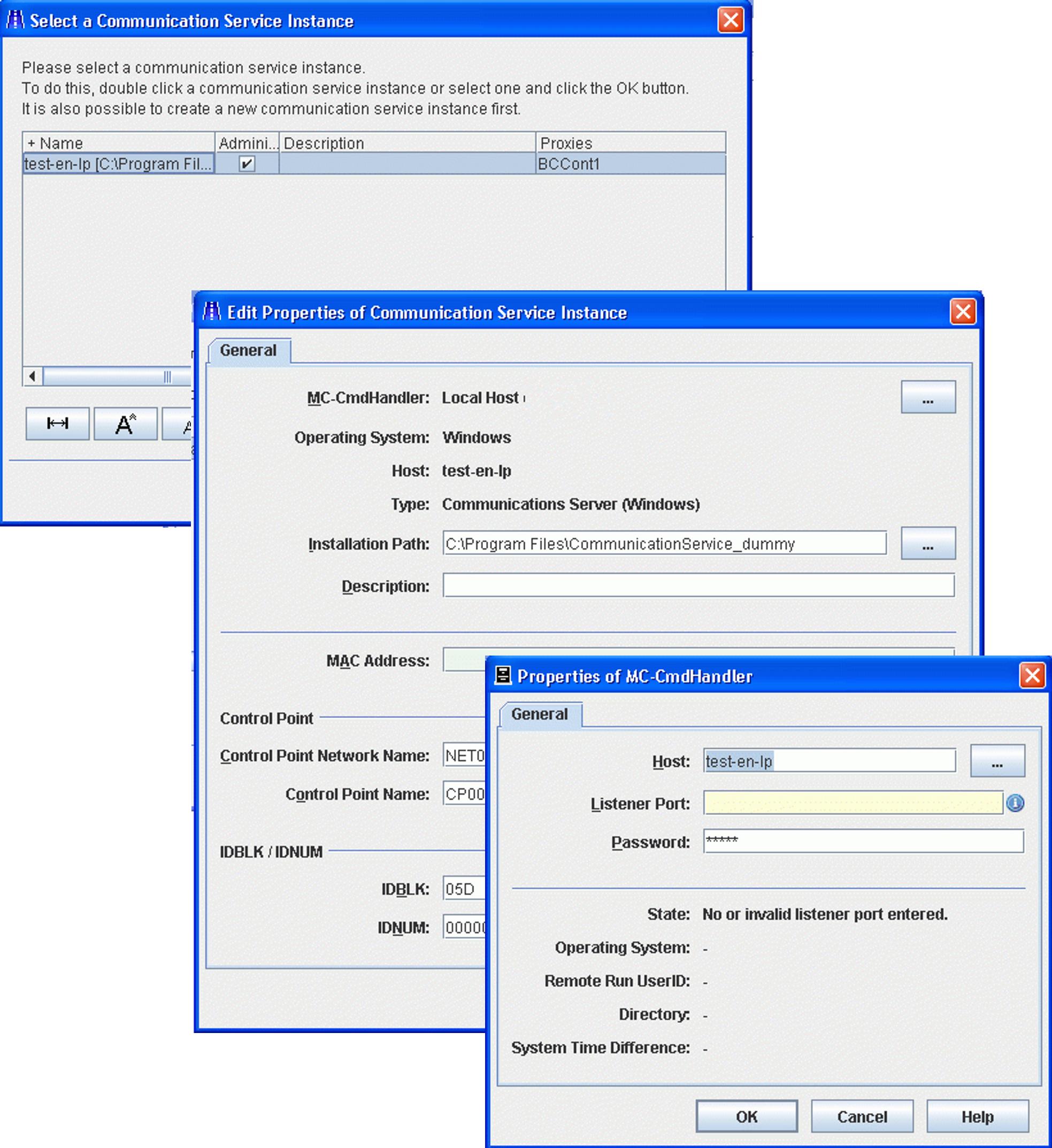
Figure 21: Configuring a communication service
The communication service instances that have already been configured are displayed in Select a Communication Service Instance. You can select an instance and click OK to assign this instance. You can click Edit to modify the properties of a selected instance.
Proceed as follows if you want to configure a new communication service instance:
Click the Add button.
In Add Communication Service Instance, click the ... button under Select MC-CmdHandler to open the dialog Properties of MC-CmdHandler.
In Properties of MC-CmdHandler, enter the properties of the MC handler used to administer the components and click OK.
In Add Communication Service Instance, enter the installation path of the communication service together with the configuration parameters (as described below) and click OK.
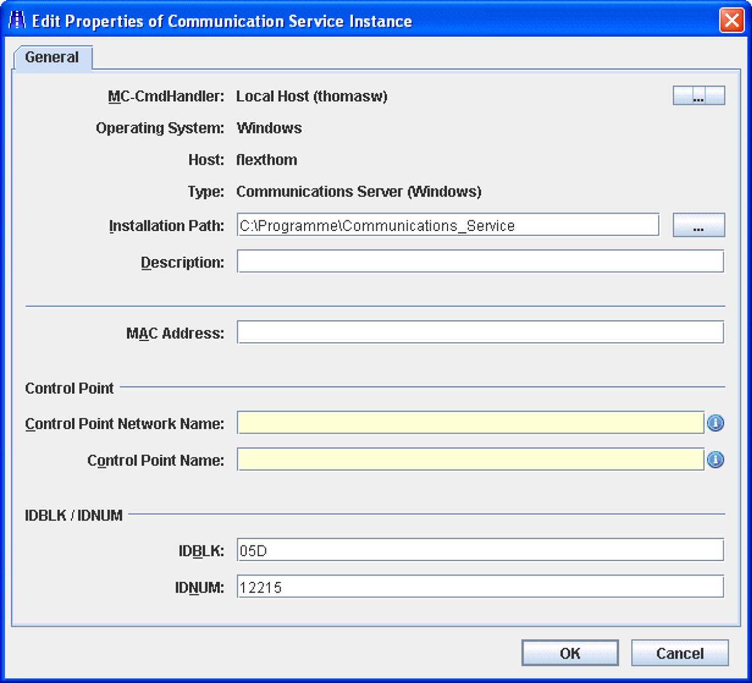
Figure 22: Configuring the properties of a communication service
MAC Address
If LAN is used as the DLC type for at least one EIS partner then you must enter the MAC address of the computer on which the communication service is running here. For more detailed information, see Adding EIS partners of the type CICS .
Control Point
The control point refers to a unique node in the SNA network. This name is used to identify the instance of the communication service. BeanConnect generates a file containing the necessary VTAM definitions which can then be entered at the z/OSTM mainframe (see Configuration of VTAM on an IBM mainframe ). The complete control point name must be unique in the network and consists of the following two parts:
Control Point Network Name specifies the network and can be freely defined by the user. It is, however, recommended that you use the EIS network name.
Control Point Name specifies the control point in this network. The name must match the VTAM definition on z/OS.
IDBLK / IDNUM
These values form the XID (node ID) and are incorporated in the PU (physical unit) definition for the VTAM generation.
IDBLK specifies the block ID (IDBLK value) for the CICS generation. It must be specified as a 3-digit hexadecimal number. Alphabetic characters must be entered in uppercase.
IDNUM specifies the Physical Unit ID (IDNUM value) for the CICS generation. It must be specified as a 5-digit hexadecimal number. Alphabetic characters must be entered in uppercase.
See the Glossary for an explanation of SNA-specific terms.