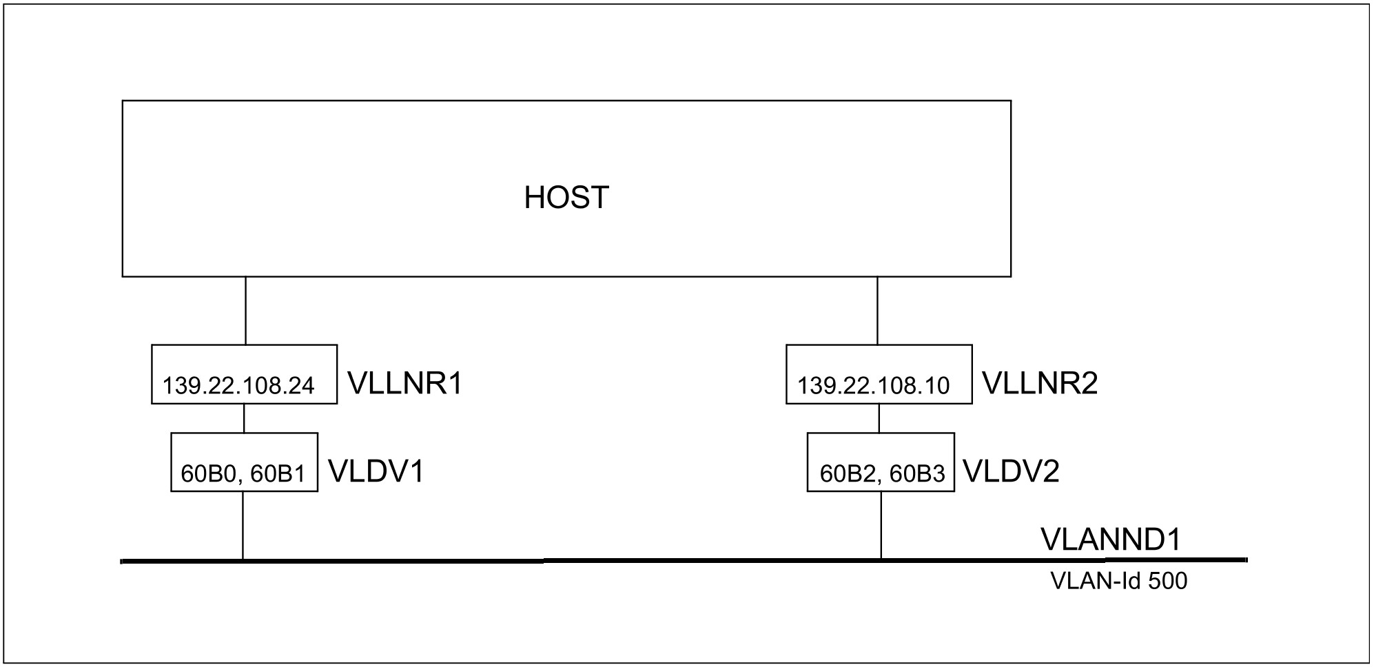
In the following a redundant VLAN configuration is presented using only BCAM commands. For this purpose two VLAN-capable device connections are available which are to be operated with tagged frame. The VLAN node is defined with VLAN-ID=500.
Dynamic generation with SDF commands
/REMARK Definition of the VLAN devices VLDV1 and VLDV2
/CREATE-VLAN-DEVICE DEVICE-NAME=VLDV1-

/ ,WRITE-DEVICE=60B0-

/ ,READ-DEVICE=60B1-

/ ,LAN-ADDRESS=*DYNAMIC-

/ ,MAX-LPDU-SIZE=*BY-DEVICE-
/CREATE-VLAN-DEVICE DEVICE-NAME=VLDV2-

/ ,WRITE-DEVICE=60B2-

/ ,READ-DEVICE=60B3-

/ ,LAN-ADDRESS=*DYNAMIC-

/ ,MAX-LPDU-SIZE=*BY-DEVICE
/REMARK Definition of the VLAN node VLANND1
/CREATE-NODE NODE-NAME=VLANND1-

/ ,IP-SUBNET-MASK=255.255.255.128-

/ ,LAN-TYPE=*VIRTUAL(-

/   VLAN-ID=500-

/   ,PRIORITY=*STD)
/REMARK Definition of the VLAN lines VLLNR1, VLLNR2
/CREATE-VLAN-LINE LINE-NAME=VLLNR1-

/ ,HOST-NAME=*STD-

/ ,NODE-NAME=VLANND1-

/ ,DEVICE-NAME=VLDV1-

/ ,IP-ADDRESS=139.22.108.24 -

/ ,AUTO-ROUTE-SWITCHING=*OFF-

/ ,ROUTE-RESWITCHING=*OFF
/CREATE-VLAN-LINE LINE-NAME=VLLNR2-

/ ,HOST-NAME=*STD-

/ ,NODE-NAME=VLANND1-

/ ,DEVICE-NAME=VLDV2-

/ ,IP-ADDRESS=139.22.108.10-

/ ,AUTO-ROUTE-SWITCHING=*OFF-

/ ,ROUTE-RESWITCHING=*OFF
Note
The definitions of the VLAN lines permit switching operations to be controlled by the AUTO-ROUTE-SWITCHING and ROUTE-RESWITCHING operands which become effective when the VLAN lines are activated. In this example the switching of the routes is suppressed, but this can be changed later with appropriate MODIFY-VLAN-LINE commands.
/MODIFY-VLAN-LINE LINE-NAME=VLLNR1,-

/ ,AUTO-ROUTE-SWITCHING=*ON-

/ ,ROUTE-RESWITCHING=*ON
/MODIFY-VLAN-LINE LINE-NAME=VLLNR2,-

/ ,AUTO-ROUTE-SWITCHING=*ON-

/ ,ROUTE-RESWITCHING=*ON
Note
A local processor, e.g. PROC#L#1, can be defined using the options described below.
Definition through AEC (automatic end system creation)
The local processor PROC#L#1 can alternately be specified in the processor file and generated by automatic end system creation. To do this the “automatic end system creation” option must be specified. In addition, the system must be included in the processor file and in the SOF file a MODIFY-VLAN-ASSIGNMENT command must be issued.
Setting options
/BCOPTION A-E-C=ON
Entry in the processor file
PROC#L#1 IP 139.22.108.135
Entries in the SOF file
/MODIFY-VLAN-ASSIGNMENT IP-ADDRESS-RANGE=*ADD-TO-VLAN (-
/FROM=139.22.108.135, TO=139.22.108.139, VLAN-ID=500)
Definition through DNS
Another way of defining the local processor PROC#L#1 is to use DNS. To do this you must start the LWRESD utility routine (by default this is already possible in the DCOPT/ DCSTART command) and specify the option for DNS. DNS accesses can be restricted using the MODIFY-DNS-ACCESS command.
Entries in the SOF file
/MODIFY-BCAM-OPTIONS DNS-OPTIONS=*PARAMETERS(DNS-USAGE=*ON)
/MODIFY-DNS-ACCESS IP-ADDRESS-RANGE= -

/*ADD(FROM=139.22.108.135,TO=139.22.108.139)
/MODIFY-DNS-ACCESS IPV6-ADDRESS-RANGE=*NONE
/MODIFY-DNS-ACCESS NAMES=PROC#L#1
/MODIFY-VLAN-ASSIGNMENT IP-ADDRESS-RANGE=*ADD-TO-VLAN (-
/FROM=139.22.108.135, TO=139.22.108.139, VLAN-ID=500)