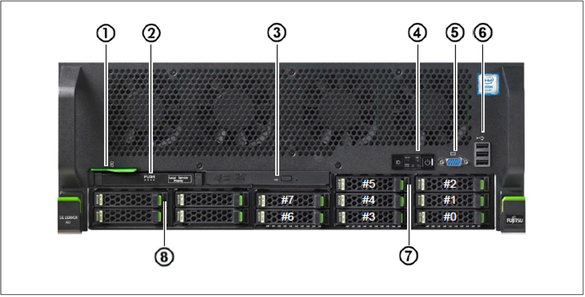
Figure 1: Application Unit (front)
No. | Meaning |
1 | ID card (green) |
2 | ServerView Local Service Display |
3 | Optical drive activity indicator |
4 | Operator control panel (for further details see figure 2) |
5 | Video port |
6 | 3x USB ports |
7 | HDD indicators; |
8 | SSD indicators; |
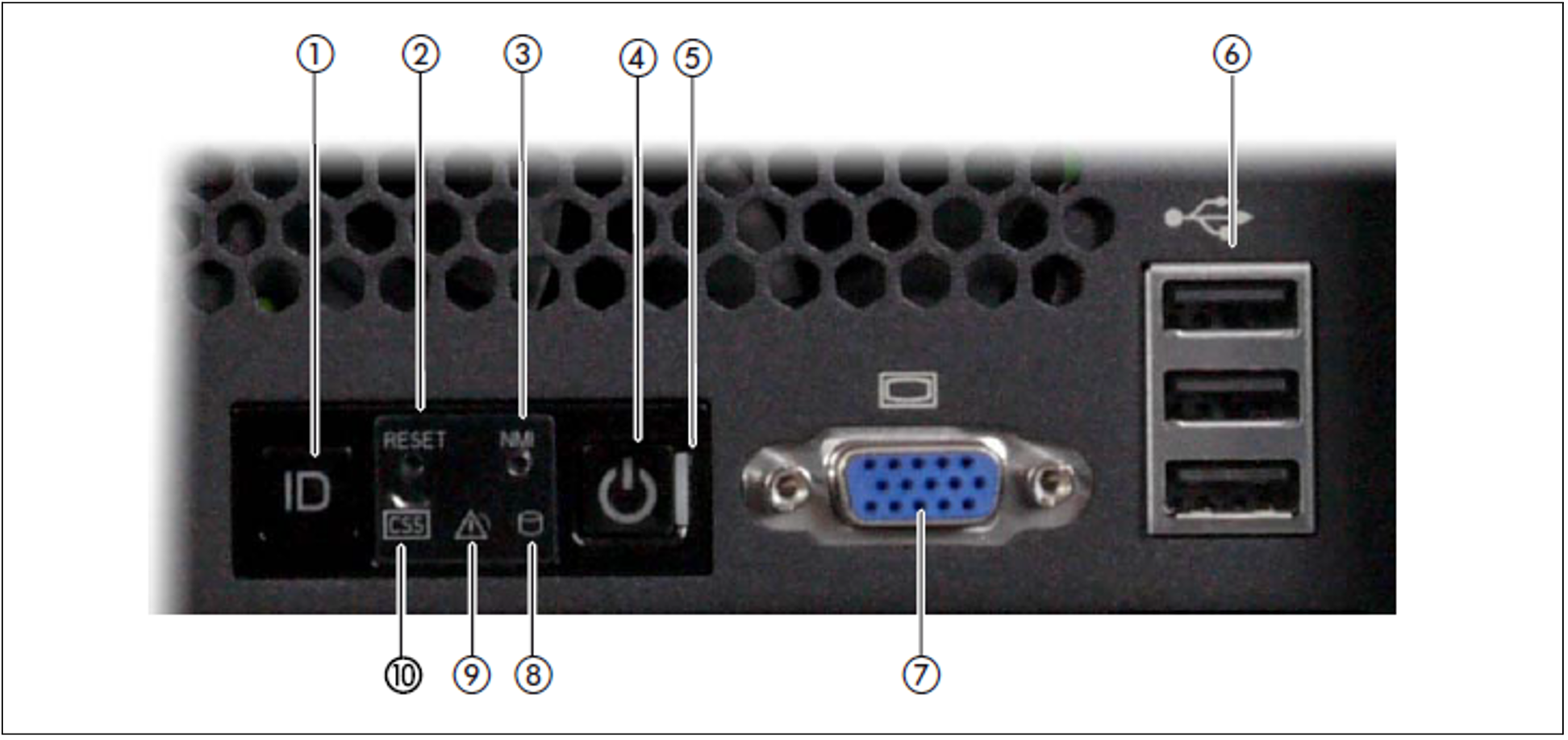
Figure 2: Front - Detailed view: Operator control panel
No. | Meaning |
1 | ID button / ID indicator |
2 | Reset button |
3 | NMI button |
4 | On/Off button / Status indicator |
5 | Status indicator (power cable connected) |
6 | 3x USB ports |
7 | Video port |
8 | HDD/SSD activity indicator |
9 | Global error indicator |
10 | CSS indicator |
ID card
You can pull the ID card (see figure 1) out and push it in again as far as it will go.
The ID card contains various system information, e.g. product name, serial number, MAC addresses and DNS name.
Controls
Control | Meaning |
ID | Identification (ID) button Lights up (blue) on the front and on the rear of the server when the ID button is pressed. The two ID indicators are synchronized. |
 | On/Off switch When the Application Unit is switched off, it is switched on again by pressing the On/Off switch once. When the Application Unit is in operation, it is switched off by pressing the On/Off switch once. CAUTION! Possible loss of data! The On/Off switch does not disconnect the server from the voltage grid. To disconnect from the mains completely, remove the power plugs. These buttons may only be used by Customer Support. |
RST or RESET | Reset button Pressing the Reset button reboots the Application Unit. CAUTION! Possible loss of data! |
NMI | NMI button CAUTION! Do not press! Possible loss of data! The NMI button may only be used by Customer Support. |
Indicators on the operator control panel
Indicator | Meaning |
ID | ID indicator (blue) Lights up blue when the Application Unit has been selected by pressing the ID button. To deactivate, press the button again. The ID indicator can also be activated via the ServerView Operations Manager and the iRMC Web GUI, and the status is reported to the ServerView Operations Manager and the iRMC. |
 | Status indicator (green) Does not light up when the Application Unit is switched off but is connected to the power supply (power cable connected). Lights up green during the power up delay and in normal system operation (S0). Status indicator (power cable connected)( green) on the right-hand side of the On/Off switch Does not light up in the following cases:
Lights up green when one of the following cases occurs:
After the Application Unit has been connected to the power source, it takes approximately 60 seconds until the Application Unit has entered standby mode. |
 | HDD activity indicator (green) |
 | Global error indicator (yellow) Lights up yellow when a prefailure event was detected which requires Customer Support to become active (by way of precaution). Flashes yellow when an error was detected which requires Customer Support to become active. Does not light up when no critical event has occurred. If the event is still acute after a power failure, the indicator is activated after the restart. The indicator also lights up in standby mode. You can obtain detailed information on the error cases displayed from the System Event Log (SEL), on the ServerView Local Service Display, in the ServerView Operations Manager or on the web interface of the iRMC. |
Indicators on the operable drives/components
Optical drive activity indicator
Lights up green when the storage medium is accessed.
ServerView Local Service Display
A tray mechanism enables you to pull the ServerView Local Service Display out of the computer housing to read information. Press the front of the module to release the lock.
You can also swing the ServerView Local Service Display out of its normal position at an angle of 120°. This makes it easier to read the information when the server is located high up in the rack.
CAUTION!
If a fault occurs, please contact Customer Support.
Hard disks
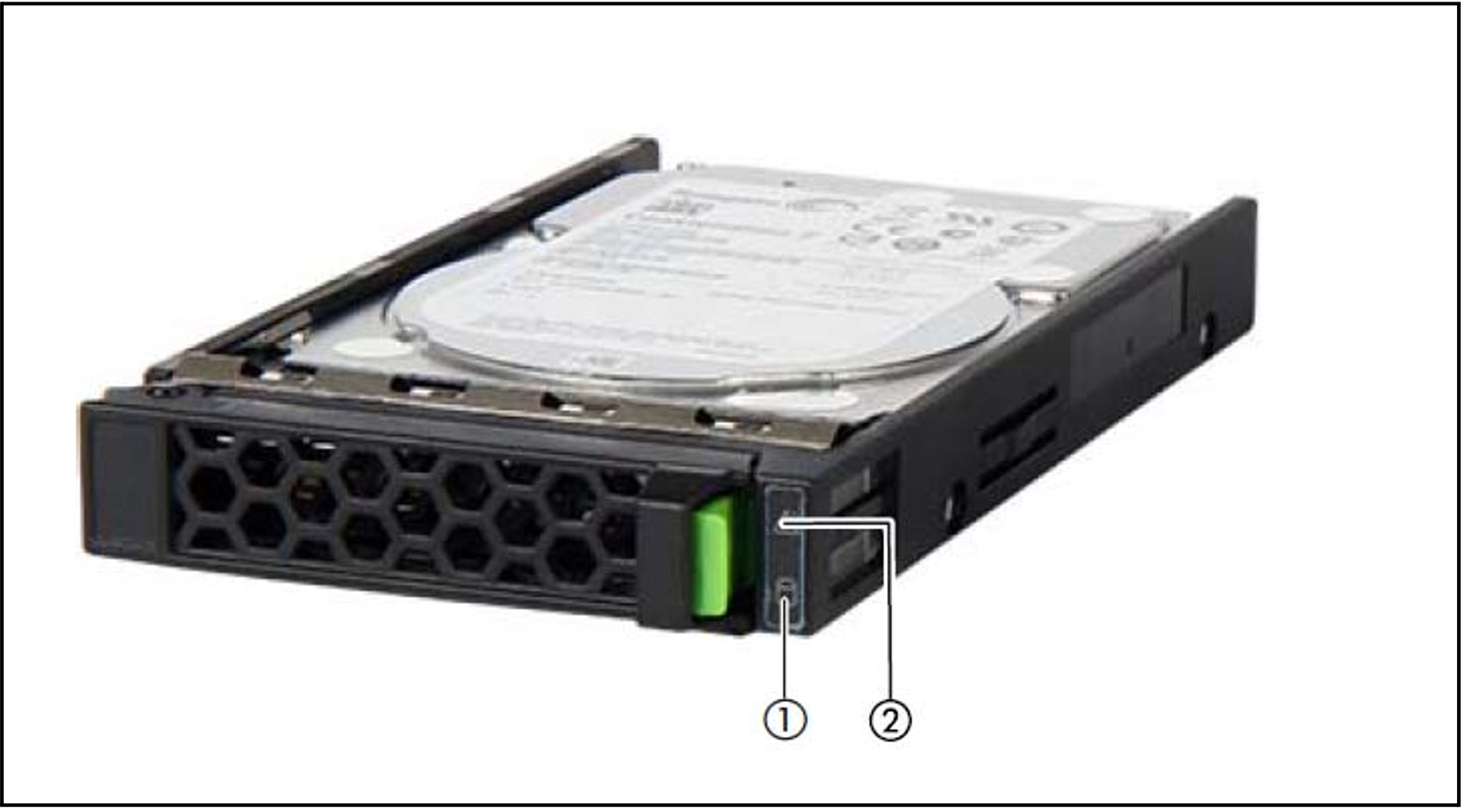
Figure 3: Indicators on a hot-plug HDD module
No. | Meaning |
1 | HDD BUSY (green)
|
2 | HDD FAULT (orange)
|
If a hard disk drive continuously indicates an error, the drive should be replaced by Customer Support as soon as possible. In this case call Customer Support.
SSD indicator
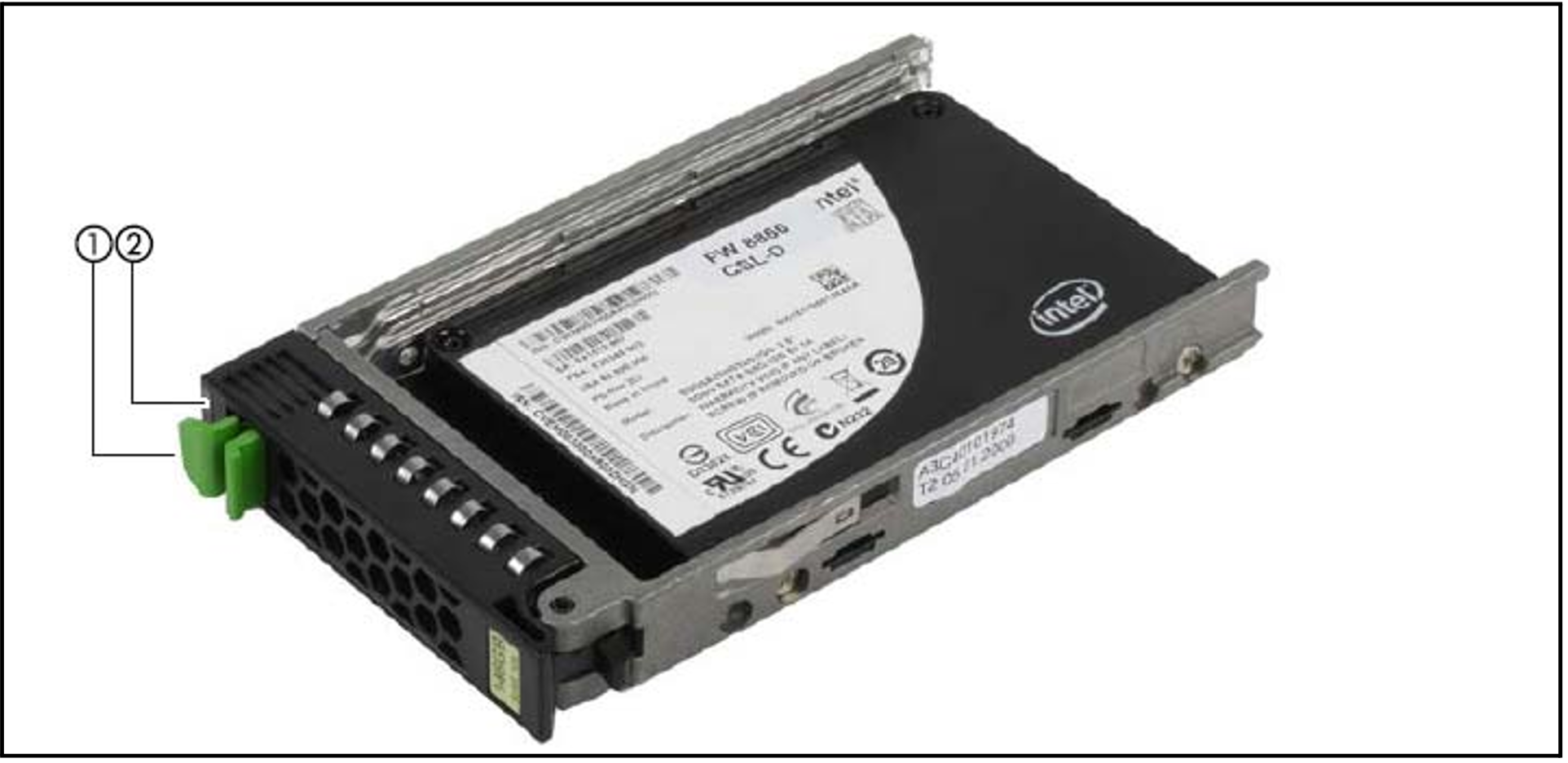
Figure 4: Indicators on the SSD drives
No. | Meaning |
1 | LED green BUSY
|
2 | LED orange FAULT (orange)
|