Loading...
Select Version
&pagelevel(3)&pagelevel
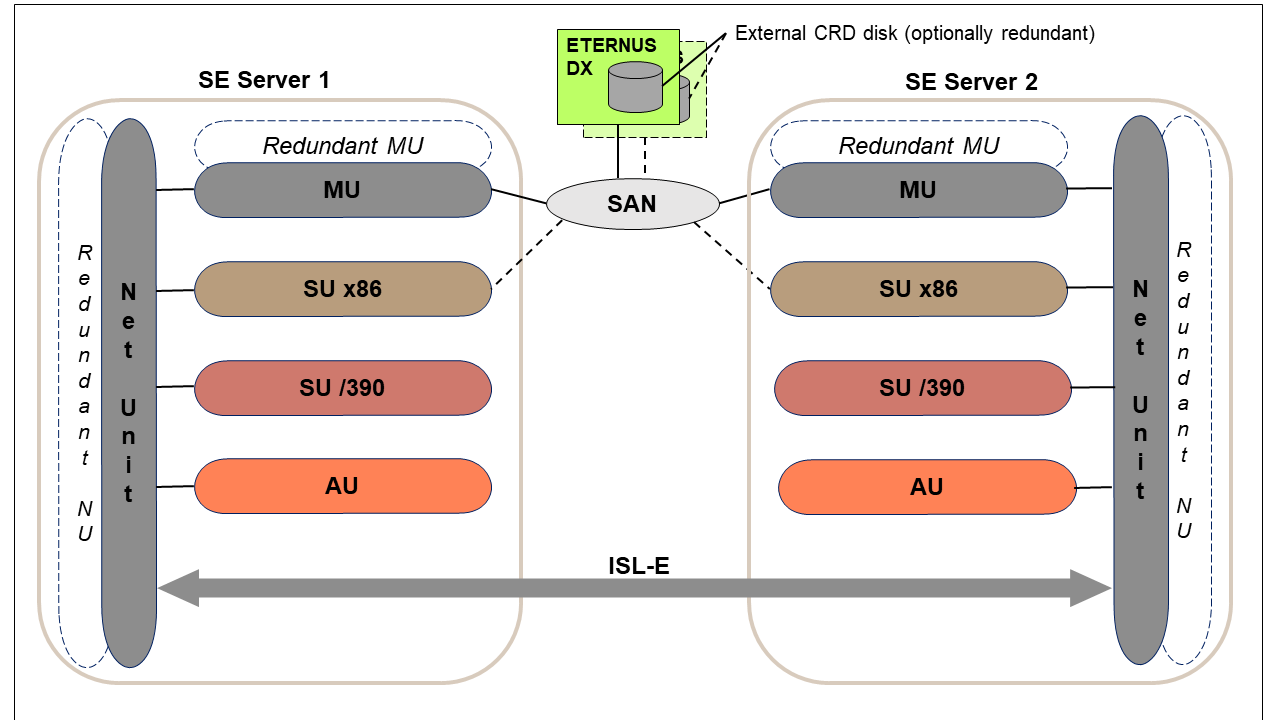
The following image contains the basic HW structure as prerequisite for cluster functions:
- Two SE Servers
- ISL-E connections between the two SE Servers
- CRD disks (configuration disks) which are accessible through SAN from all units on which they are needed.
This is the basic HW structure for the following cluster functions:
- Management Cluster (SE Cluster)
- SU /390 Cluster (SU Cluster with SU /390)
- SU x86 Cluster (SU Cluster with SU x86)
Notice - Management Cluster with >= 2 SE servers on 2 locations
- Also, more than two SE servers can be connected to a Management Cluster.
The participating SE servers must be distributed over a maximum of two locations. - The basic HW structure must be extended accordingly.
As of three connected SE servers new questions regarding the optimal network connection arise, that must be solved individually.
If needed, the customer service will support you doing this. - In case of a larger Management Cluster, the menu of SEM is extended according to every SE server. Because there are no functional differences, the descriptions and examples in this document always assume a Management Cluster with two servers.

