To add a new EIS partner:
Click the Add button beneath the list of EIS partners or choose Add EIS Partner from the context menu of an existing EIS partner object or the EIS Partner node.
If the proxy/proxy cluster is configured for the two partner types (UTM and CICS), then the dialog box Choose EIS Partner Type is displayed during this operation. Here you must choose UTM application.
Define the properties for the EIS partner. The property sheet is opened automatically and contains the tabs General, UTM Partner and Availability Check.
The following properties are requested:
General tab (UTM Partner)
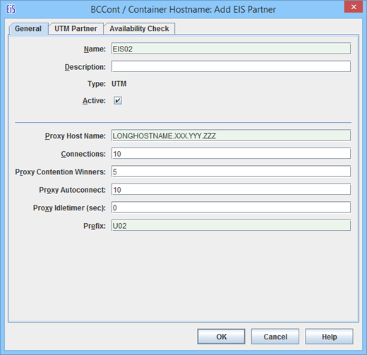
Figure 30: General properties of an EIS partner of Type openUTM
Name / Description
Name is the name of the EIS partner. This must be unique to the proxy. Additionally, you can enter a Description for the EIS partner. For a created EIS partner, the EIS ID is shown beneath the name. (cannot be changed).
Type
Displays the type of EIS partner: here UTM, cannot be changed.
Active
The option Active controls whether the EIS partner definition is active or not. Only active EIS partners will be included in the configuration of the proxy and the EIS partner (Update Configuration command in the proxy node or proxy cluster node).
Proxy Host Name
FQDN (full qualified DNS name) of the host on which the proxy is located and under which it is known in the UTM partner application (max. 64 characters).
In the case of an EIS partner in the proxy cluster, there is an entry field for each cluster proxy in which you must specify the computer name under which the corresponding proxy is known to the EIS partner.
By default, this field is set to the computer name entered under General for Host in the Edit Properties command. If an IP address was specified for the proxy host then this must be replaced by the name
Connections
Specifies the maximum number of concurrent connections allowed between proxy and the EIS partner.
Proxy Contention Winners
Specifies the number of connections for which the proxy should be contention winner. The number you should specify depends on the favored communication type (outbound or inbound communication).
The following applies in principle:
Outbound communication: the proxy should be the contention winner.
Inbound communication: the EIS partner should be the contention winner.
Proxy Autoconnect
Defines the number of connections to be established when starting the proxy.
Proxy Idletimer (sec)
Specifies the time in seconds after which the BeanConnect proxy container is to clear down the connection to the EIS partner if no communication has taken place over the connection during that time.
Possible values: 0 (default) through 32767.
0 means that the timer is not used.
Prefix
The prefix is included as a component in names which are used in configuration statements. This prefix must be unique for all proxies running on the same host. The prefix must comprise exactly three characters (uppercase letters or digits). The first character must be an uppercase letter.
UTM Partner tab
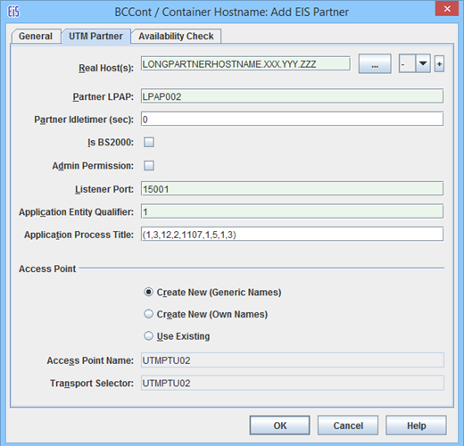
Figure 31: Properties of the UTM partner
If expert mode is enabled then additional fields are displayed. These are described later on, see "UTM Partners - Additional Fields in Expert Mode".
Real Host(s)
FQDN (full qualified DNS name) of the host on which the UTM partner application is located, 1 to a maximum of 64 characters.
If the partner application is an UTM cluster application, enter the names of the computers and, if required, the mapped host names of all the cluster nodes here.
Alternatively, you can click the "..." button to specify the address of the host (instead of its name).
If the partner is an UTM cluster, specify the cluster node index of the node application in the drop-down list to the right of the button.
If the partner is a stand-alone UTM application, select “-“ in the drop-down list.
The node index of the cluster node is determined by the sequence of CLUSTER-NODE statements in the KDCDEF input of the cluster partner application. The node that is defined by the first CLUSTER-NODE statement has the index 1, the node corresponding to the second CLUSTER-NODE statement has the index 2 and so on.
If the partner is an UTM cluster, click the button + (plus) to add a further cluster node. An additional row with the same structure as the first row is now displayed. Click the button - (minus) to remove a cluster node from the configuration again. You can specify a maximum of 32 cluster nodes. You cannot remove the last remaining cluster node.
Partner LPAP
Specifies the LPAP name under which the UTM partner application addresses the BeanConnect proxy and therefore also the application server during inbound communication, 1 to a maximum of 8 characters in length. From this name, the Management Console generates an OSI-LPAP statement for generating the UTM partner application.
Partner Idletimer (sec)
Specifies the time in seconds after which the EIS partner is to clear down the connection to the BeanConnect proxy container if no communication has taken place over the connection during that time.
It is recommended that you choose a value for Partner Idletimer that is smaller than the one specified for Proxy Idletimer.
0 means that the timer is not used.
Possible values: 0 (default) through 32767.
Is BS2000
This option specifies whether or not the UTM partner application is located on a BS2000 system. If this option is activated then the Management Console generates KDCDEF and BCMAP statements for a BS2000 system.
If this option is not enabled then the Management Console generates the KDCDEF statements and the host name file for Unix, Linux and Windows platforms.
Admin Permission
This option specifies whether the proxy, and, implicitly, the application server also, are to possess administrative permissions in the UTM partner application during outbound communication.
Listener Port
Defines the port at which the UTM partner application waits for requests to establish a connection. Permitted values: 102 and 1025 through 32767
If you have not enabled Is BS2000 and you select the Use Existing option for Access Point, you must enter the value generated in the UTM partner application here (ACCESS-POINT statement, LISTENER-PORT operand).
Application Entity Qualifier
The Application Entity Qualifier is an address component for the UTM partner application's access point.
If you select the Use Existing option for Access Point, you must enter the value generated in the UTM partner application here (ACCESS-POINT statement, APPLICATION-ENTITY-QUALIFIER operand).
Application Process Title
The Application Process Title is an address component for the UTM partner application's UTMD statement.
If you select the Use Existing option for Access Point, you must enter the value generated in the UTM partner application (UTMD statement, APPLICATION-PROCESS-TITLE operand).
If the EIS partner is a UTM cluster application and the specified application process title (APT) consists of fewer than 10 elements then the Management Console adds the node index to the APT in order to ensure that the APTs are unique.
Access Point
Defines the properties of the access point used to address the UTM partner application during outbound communication. The access point is generated in the UTM partner application using the KDCDEF statement ACCESS-POINT.
The three options Create New (Generic Names), Create New (Own Names) and Use Existing are used to determine whether the Management Console generates KDCDEF statements for the access point, or whether an access point that already exists in the UTM partner application is to be used.
Create New (Generic Names)
If you select this option, the Management Console generates an ACCESS-POINT statement with generic values. The Management Console enters these values in the Access Point Name, Transport Selector and Transport Selector Format fields. They cannot be changed.Create New (Own Names)
If you select this option, the Management Console generates an ACCESS-POINT statement with specific values. The Management Console enters these values in the fields Access Point Name, Transport Selector and Transport Selector Format. You can modify the values.Use Existing
If you select this option, the Management Console does not generate an ACCESS-POINT statement. This option is designed for circumstances in which you want to use an existing access point in the UTM partner application. You must enter the values for this access point in the Access Point Name, Transport Selector and Transport Selector Format fields. Furthermore, the values you enter in the Application Entity Qualifier and Listener Port fields must have been generated in the UTM partner application.Access Point Name
Name of the access point in the UTM partner application.If you select Create New (Generic Names), this contains the generated name (cannot be changed).
If you select Create New (Own Names), you must enter a freely-definable name here (1 through 8 characters in length).
If you select Use Existing, you must enter the name generated in the ACCESS-POINT statement of the UTM partner application.
Transport Selector
Transport selector of the access point in the UTM partner application.
If you select Create New (Generic Names), this contains the generated name (cannot be changed).
If you select Use Existing, you must enter the name generated with T-SEL= in the ACCESS-POINT statement of the UTM partner application.
If you select Create New (Own Names), you must enter a freely-definable name here.This can be 1 through 8 characters in length, the first character must be an uppercase alphabetic character, otherwise alphabetic characters, numeric characters and the special characters #, $ and @ are permitted.
UTM Partners - Additional Fields in Expert Mode
If expert mode is active then the following additional fields are also displayed:
Application Program Interface Mode of EIS Partner
This field is only relevant for partners that use the XATMI interface, see Configuring EIS partners of type XATMI . In the case of UTM partner applications that use the KDCS interface, the value Standard must always be set for API Mode.
Transport Selector Format
Format used to encode the transport selector.If you select Create New (Generic Names), this contains the generated value (cannot be changed).
If you select Create New (Own Names), you can choose between ASCII, EBCDIC and TRANSDATA (default). If the EIS partner is running under a BS2000 system, TRANSDATA must be used as the transport selector format.
If you select Use Existing, you must enter the value generated with TSEL-FORMAT= in the ACCESS-POINT statement of the UTM partner application.
Availability Check tab (UTM partner)
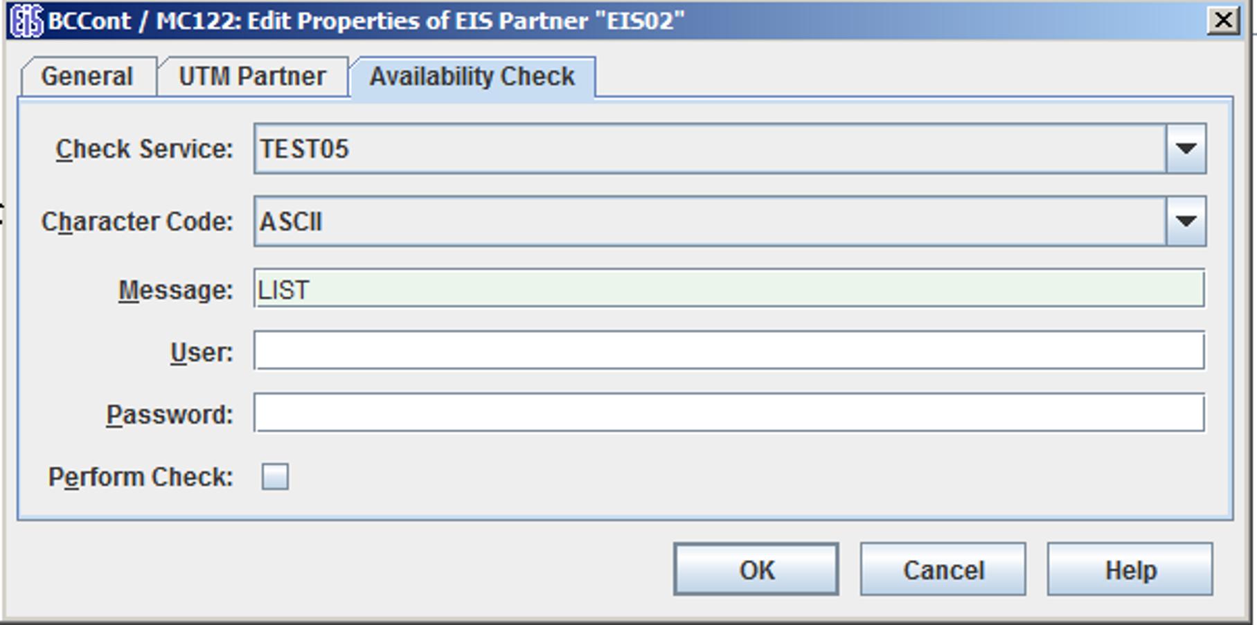
Figure 32: Properties of the EIS partner for the availability check
This dialog box allows you to select a dialog service in the partner application which is called when checking the availability of an EIS partner. When this is done, the message defined in Message is passed to the specified service in the EIS partner. As soon as the response is received, the EIS partner is flagged as available. The response is output in the Management Console.
You cannot complete this dialog box properly unless you have defined at least one outbound service for the EIS partner, see Configuring outbound services .
Check Service
This lists all the outbound services defined for this partner. Select a suitable service from the list. The service is always of type Dialog.
Character Code
Character set used by the EIS partner:
Possible values: ASCII or EBCDIC.
Message
Message sent to the EIS partner when checking availability. The maximum length of the message is 80 characters.
User
User ID if the service is to be called under a specific user ID.
Password
Password for the user ID if a password is required.
Perform Check
This option allows you to temporarily disable the availability check for this EIS partner without losing the settings, such as the service to be called.
If the option is enabled, the availability check is performed with the specified parameters.
If you disable this option, the availability check for this EIS partner is disabled until the option is enabled again. Both automatic availability checking and the availability check performed by issuing a command in the proxy or proxy cluster's context menu are disabled. If the EIS partner is checked "manually" (using its context menu), the check is performed irrespective of this setting.