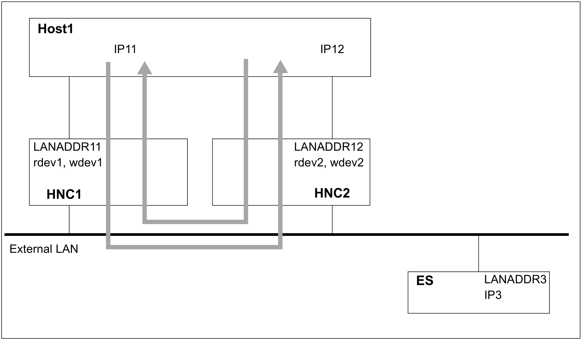
In the figure below the BS2000 server "Host1" (IP addresses "IP11" and "IP12", LAN addresses "LANADDR11" and "LANADDR12") and the end system "ES" (IP address "IP3", "LANADDR3") are linked via the HNCs "HNC1" and "HNC2" and a real network.
Line monitoring
The arrows in the diagram show how line monitoring functions in principle. Two tests are used for this purpose:
Incoming messages are time monitored by sending monitoring messages which are expected at regular intervals on the receiving side.
Outgoing messages are monitored directly by detecting I/O errors.
General information on the configuration
If a dummy address such as 10.1.1.3 is specified for line monitoring for IP12, this line is not used productively
If both lines are to be used productively, both addresses must be made visible on the outside. It is possible that one part of the end systems uses the address of the 1st line and the other part the address of the 2nd line. When one line fails, the routes are transferred to the line which is still operational.
AUTO-ROUTE-SWITCHING and ROUTE-RESWITCHING must be set to *ON to permit the routes to be switched over and back:
If the operands are already set in the CREATE-LINE or CREATE-VLAN-LINE command, the switchover is performed when activation takes place as lines and VLAN lines are activated one after another.
If the operands are set later using a MODIFY-LINE or MODIFY-VLAN-LINE command, switching operations are prevented when activation takes place. This procedure is consequently recommended.
As a rule both lines should already be active after the ACTIVATE-LINE or ACTIVATE-VLAN-LINE command. Switching operations (for local IP addresses) are executed only after the MODIFY-LINE or MODIFY-VLAN-LINE commands. If one line unexpectedly does not become active, the BCACT command takes effect for the node and permits the switching operation to take place.
A BCACT command for the node activates the network which, from the BCAM viewpoint, is situated behind this node. Only then is connection setup from the network possible via this node.
You should use the ACTIVATE-LINE and DEACTIVATE-LINE commands to activate and deactivate lines as these leave the line settings you have made unchanged, in contrast to the line-specific BCACT and BCDAC commands.