The figure below shows the hardware involved in switching the Server Unit /390 on/off.
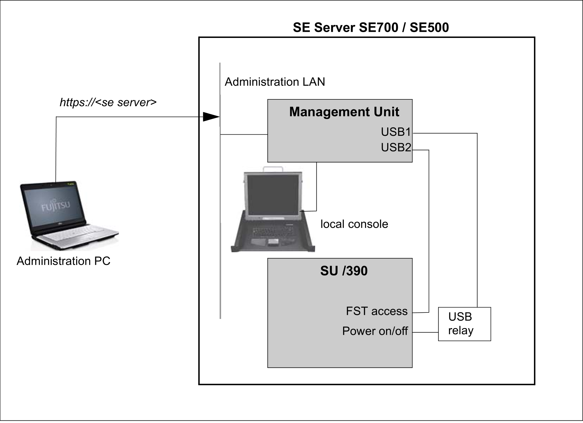
Figure 32: Hardware involved in switching the Server Unit /390 on/off
Detailed information on switching the hardware on/off using the SE Manager is provided in the "Operation and Administration" manual [5].
The following hardware components must be switched on in the specified order.
1. Switch on the optional hardware components
> | Switch on the ETERNUS LT40 S2 tape library using the On/Off switch at the front (see the "Additive Components" Operating Manual [4]). |
> | Switch on any other connected hardware components. |
2. Switch on the MU
The power-on indicator (item 11 in figure10) lights up orange (POWER STAND-BY).
> | Switch on the rack console by pulling out and folding out the monitor, see "Rack console". |
> | Press the On/Off switch on the MU (item 12 in figure 10). The power-on indicator lights up green. The MU switches itself on, conducts a system test and starts the M2000 software. This takes a little time. Finally, on the rack console you see the login window for the Linux desktop of the local console. |
> | Call the SE Manager, e.g. after logging in on the local console via the browser of the Linux desktop (in the “Computer” menu in the task bar) or via an administration PC (default), see the “Operation and Administration” manual [5]. |
Redundant MUs are switched on in the same way.
You can also switch on the MU remotely via the iRMC of the MU, see the “Operation and Administration” manual [5].
3. Switch on the Server Unit SU /390
> | As the administrator, BS2000 administrator or a privileged operator, switch on the Server Unit using the SE Manager (menu Hardware |
Alternatively you can switch the Server Unit on by pressing the POWER ON button on the server's control panel (see "Control panel (on the SE700 and SE500)"). The system is ready when the status indicator on the server's control panel displays no further error codes.
Then you can call an SVP console window in the SE Manager and start the BS2000 system using PROGRAM LOAD FRAME: DETAIL-1.
When a POWER ON IPL is configured, the BS2000 system is loaded automatically (using AUXILIARY FRAME: LOAD PRESET1).
Alternatively the IPL can also be initiated in the SE Manager (see the menu Systems -> [ <se server> (SE<model>) -> ] <unit> (SU</390>) -> BS2000 operation mode, “Operation and Administration” manual [5]).
The control panel and SVP frames of the Server Unit are described in the "Server Unit/390" Operating Manual [2].
4. Switch on the optional Server Units x86
Before the Server Unit is switched on, the status indicator lights up orange.
> | Switch on the Server Unit by pressing the On/Off switch. The power-on indicator lights up green. The Server Unit switches on, conducts a system test and starts X2000. If automatic IPL is configured for BS2000, the BS2000 system (Native or as a VM2000 monitor system) is also started with the configured settings. If automatic startup is configured for XenVMs, these systems are also started. |
The controls and indicators of the Server Unit are described in the "Server Unit x86" Operating Manual [3].
Further Server Units x86 are switched on in the same way.
5. Switch on the optional Application Units
Before an Application Unit is switched on, the status indicator lights up orange (POWER STAND-BY).
> | As the administrator or AU administrator, switch on the Application Unit using the SE Manager (menu Hardware Alternatively, switch on the Application Unit by pressing the On/Off switch. The power-on indicator lights up green. The Application Unit switches on, conducts a system test and starts the operating system. |
The controls, indicators and further on/off options for the AU are described in the "Additive Components" Operating Manual [4].
Further Application Units are switched on in the same way.